PedroPO said:what can happen with this kind of DC tension? Loudspeaker failiure?
100mV is IMO not enough to damage speakers. Correct me if I'm wrong...
The 100mV is coming from the old channel. So replace the same cap you replaced to solve the hum prob.
Also replace C202 and is brother on the other side.
Keep us informed!😉
/Hugo - Hates hum & offset
 🙂
🙂Netlist said:
Also replace C202 and is brother on the other side.
The cap that I replaced before where precisely C202, just after the volume pot. I actually did replace both channels.
I (wildly)guess that the dc offset comes from the power transistors.
(is this even possible?)
PedroPO said:
The cap that I replaced before where precisely C202, just after the volume pot. I actually did replace both channels.
I (wildly)guess that the dc offset comes from the power transistors.
(is this even possible?)
If offset remains after power off, it must come from a cap; again correct me if I'm wrong. Only caps keep their voltage for a longer period of time. What about C262 (guess, hard to read) and (or)his brother? And C204 and brother? Or them sisters?
/Hugo - still doesn't know the gender of a cap.😉
No, 100mV is not enough to damage speakers, but it is enough to bias the speaker into slight non-linearity. More important, the 100mV offset is enough to add considerable distortion products.
PedroPO, the offset appears at the output pair, but it is the job of the input pair to 'see' this DC offset and correct for it (feedback). The input pair (in your schematic, Q201 & Q202) are supposed to take care of the offset you see. The 2SC945's that your schematic calls for are obsolete, I believe, which is why I recommended the 2SC2547.
Read here, especially section 5.
Exact DC balance of the input differential pair is essential for minimum distortion. It seems almost unknown that even minor deviations from equality of collector current (Ic) in the input devices seriously upset the 2nd-harmonic cancellation
PedroPO, the offset appears at the output pair, but it is the job of the input pair to 'see' this DC offset and correct for it (feedback). The input pair (in your schematic, Q201 & Q202) are supposed to take care of the offset you see. The 2SC945's that your schematic calls for are obsolete, I believe, which is why I recommended the 2SC2547.
Read here, especially section 5.
100mV offset
Hi Pedropo,
I would simply replace the input differential pair or better match the transistors.......
Hi Pedropo,
I would simply replace the input differential pair or better match the transistors.......
EchoWars said:PedroPO, the offset appears at the output pair, but it is the job of the input pair to 'see' this DC offset and correct for it (feedback). The input pair (in your schematic, Q201 & Q202) are supposed to take care of the offset you see.
Am I missing something here or is it possible that the offset still remains after power off if the input diff-pair is mismatched?
To me this is possible if the amp is working, but with power off????
Hugo
There looks to be no output relay, and I can see no power resistor being used to drain the PS electrolytics when power is removed, so it could possibly take a few minutes for the DC supply to drop.
Given enough time, it should drop to zero. Voltage can't exist if none is applied (other than static).
Given enough time, it should drop to zero. Voltage can't exist if none is applied (other than static).
How about putting a small potentiometer between R205 and the diff pair (instead of the T-connection)? This would give the ability to adjust the current ratio between the two legs.
/Marcus
/Marcus
EchoWars said:There looks to be no output relay, and I can see no power resistor being used to drain the PS electrolytics when power is removed, so it could possibly take a few minutes for the DC supply to drop.
Given enough time, it should drop to zero. Voltage can't exist if none is applied (other than static).
Still can't get it:
1 Power up the amp
2 Measure the DC at both outputs
3 On output 1 you measure 3mV
4 On output 2 you measure 100mV
5 Turn off the power
6 Measure again
7 On output 1 you measure 3mV or 0mV? (Don’t know)
8 On output 2 you measure 100mV
9 Short the output with the 100mV for 5sec.
10 Remove the short
11 Measure the output again: 90mV
Conclusion, to me: If the offset comes from the PS caps the 100mV would be on both outputs (no separate PS's)
Mismatched input pairs can and will give you DC-offset if the
amp is powered. But not if the power is off.
PS caps COULD give DC offset at power off but then both outputs should measure about the same output offset or is THIS statement wrong?
/Hugo
Shorting the output with the power turned off might not do any difference as all devices are turned off. Instead, try to bleed the rectifier caps after power is removed and when both voltages read 0 V then measure output DC. It should then be 0 V.
/Marcus
/Marcus
While this might balance the pair, the emitters would no longer be at the same potential, as a portion of the potentiometer between the emitter and the wiper would act as local feedback, seriously reducing gain and crippling the ability of the pair to correct for non-linearities. A drastic rise in distortion will result.e96mlo said:How about putting a small potentiometer between R205 and the diff pair (instead of the T-connection)? This would give the ability to adjust the current ratio between the two legs.
/Marcus
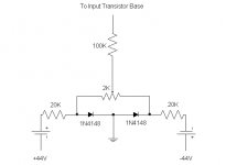
Attached is a drawing of a small circuit I added to an old Kenwood to correct for 42mV of output offset. No big thing, but I wanted perfect DC offset for its particular application. The 100K resistor may be attached to either the input transistor or the feedback transistor...depends on the sensitivity of the amp. I attached my circuit to the input transistor. I also added a .18uf film cap between the pot wiper and ground, not shown in the drawing.
Attachments
offset
Hi Pedro,
Just a suggestion: before a massive replacement program, did you consider *measuring* the various voltages shown in the schematic, to find out exactly where it is wrong. That way, you/we can target the culprit. Seems a bit more intelligent than a blind attack on everything. Start with the base voltages of the input pair against ground. You will find a imbalance there. From there on, it will be downhill.
Jan Didden
Not a bad idea, but we have been assuming here that the only problem is a collector current mismatch between the input pair. However, if you consider the amount of base current necessary to create a differential output of 100mV, it is unlikely that a DC measurement will display anything out of the ordinary.
Re: offset
Great Idea! I notice them, but didn't give much attention. Maybe It's the rigth path.
janneman said:Hi Pedro,
Just a suggestion: before a massive replacement program, did you consider *measuring* the various voltages shown in the schematic, to find out exactly where it is wrong. That way, you/we can target the culprit. Seems a bit more intelligent than a blind attack on everything. Start with the base voltages of the input pair against ground. You will find a imbalance there. From there on, it will be downhill.
Jan Didden
Great Idea! I notice them, but didn't give much attention. Maybe It's the rigth path.
EchoWars said:Not a bad idea, but we have been assuming here that the only problem is a collector current mismatch between the input pair. However, if you consider the amount of base current necessary to create a differential output of 100mV, it is unlikely that a DC measurement will display anything out of the ordinary.
We'll only know for shure when we try it, right?
Jan Didden
Hi
Interesting old thread!
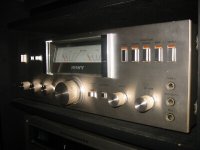
Especially as I blew up my Sony TA515 last weekend. Sniff..sniff...
I use it as a test amp. Does anyone know where I might find a schematic? There is no evidence of escaped smoke or overheating of any kind.
Its really a pity as the old amp has been very faithful for a really long time. And it looks really awesome.
rgs, Stuart
Interesting old thread!
Especially as I blew up my Sony TA515 last weekend. Sniff..sniff...
I use it as a test amp. Does anyone know where I might find a schematic? There is no evidence of escaped smoke or overheating of any kind.
Its really a pity as the old amp has been very faithful for a really long time. And it looks really awesome.
rgs, Stuart
Attachments
- Status
- Not open for further replies.
- Home
- Amplifiers
- Solid State
- Help on sony Amplifier