Hi, good evening to everyone!
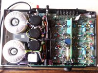
I need help on my Rega Elicit MK1, in the photo.
I bought it 'dead' from England and I have now rename it 'the resurrected'.
After 18 months, an electronic specialized laboratory - where I send it - tell me: "this amp is too ruined to be repaired". Sic! 😡
No!!! - I think - Well, then I have to do myself! 😎
With extreme patience and without an oscilloscope I have changed and replaced with original part:
all final transistors (2SC2922-2SA1216 Sanken);
all driver and pre-driver transistors (BD140-BD139 Motorola);
some small BC546b and BC556b (Fairchild);
all electrolitic capacitors (Samwha);
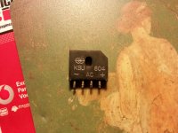
one rectifier bridge KBU804 (?);
one resistor 10ohm 3w, on right output;
and finaly many board tracks remakes, specially under BD transistors.
Only to do: 4 x 22.000uF 50v capacitors and 50KAx2 Alps pot. replacement.
Now the Elicit playing, and also good enuogh! 😛
But there are some questions! 😕
1) What is the BIAS current for the Elicit and How should I adjust with trimmer (wath value) ?
2) What is the Brand of this rectifier bridge KBU804, in the photo, and where can I find it, also used ?
3) There are some S.O.T. resistors on the board (so as on the schematic): I do not understand their function. Perhaps: Set the 0 mV offset current ? Booo ?
4) There is a blu/yellow trimmer, near the dc regulator LM78L05: How should I adjust (wath value) ?
Can someone help me ?
Thak You very very very much !!! 🙂
I need help on my Rega Elicit MK1, in the photo.
I bought it 'dead' from England and I have now rename it 'the resurrected'.
After 18 months, an electronic specialized laboratory - where I send it - tell me: "this amp is too ruined to be repaired". Sic! 😡
No!!! - I think - Well, then I have to do myself! 😎
With extreme patience and without an oscilloscope I have changed and replaced with original part:
all final transistors (2SC2922-2SA1216 Sanken);
all driver and pre-driver transistors (BD140-BD139 Motorola);
some small BC546b and BC556b (Fairchild);
all electrolitic capacitors (Samwha);
one rectifier bridge KBU804 (?);
one resistor 10ohm 3w, on right output;
and finaly many board tracks remakes, specially under BD transistors.
Only to do: 4 x 22.000uF 50v capacitors and 50KAx2 Alps pot. replacement.
Now the Elicit playing, and also good enuogh! 😛
But there are some questions! 😕
1) What is the BIAS current for the Elicit and How should I adjust with trimmer (wath value) ?
2) What is the Brand of this rectifier bridge KBU804, in the photo, and where can I find it, also used ?
3) There are some S.O.T. resistors on the board (so as on the schematic): I do not understand their function. Perhaps: Set the 0 mV offset current ? Booo ?
4) There is a blu/yellow trimmer, near the dc regulator LM78L05: How should I adjust (wath value) ?
Can someone help me ?
Thak You very very very much !!! 🙂
Attachments
Welcome to diyAudio 🙂 You have done well.
1/ The blue multi-turn trimmers appear to be for bias adjustment. Recommended value is unknown without a manual. If we knew the output configuration and components values we could hazard a good guess at the theoretical value but that could be way over what the amp is designed for due to thermal constraints (not enough heatsinking).
2/ The rectifier looks to be a generic type available anywhere. Possibly 800 v 4 amp rated.
3 and 4/ We would have to see the full circuit diagram to even guess.
Well done though. Its a very complex amp.
Hi, thank You.
Yes the multi-turn trimmer is for bias adjustment, but I don't know the correct value.
Actually the value is 3mV across the two 0.47 R Emitter resistors, for each channel.
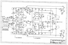
I post, for left channel, Power amp (1 SOT resitor ?), Disc input (2 SOT resistors ??) and Power supply (blu/yellow WAS trimmer ?) schematics. The right channel is identical.
Thaks very much !!!
Yes the multi-turn trimmer is for bias adjustment, but I don't know the correct value.
Actually the value is 3mV across the two 0.47 R Emitter resistors, for each channel.
I post, for left channel, Power amp (1 SOT resitor ?), Disc input (2 SOT resistors ??) and Power supply (blu/yellow WAS trimmer ?) schematics. The right channel is identical.
Thaks very much !!!
Attachments
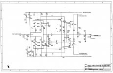
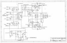
The theoretical bias current would be in the 50 to 60 milliamp region for the power amp and so that would be around 28 millivolts across each 0.47 ohm. Check that with no speaker and no signal. If it seems to get to hot with that current then you will have to compromise and go lower. That depends how good the heatsinking is.
The SOT trimmers set the DC offsets to zero volts.
For the power amp the trimmer sets the DC voltage across the speaker outputs to zero volts.
For the disc input the left SOT sets TP14 to zero volts and the second SOT sets TP 12 to zero volts DC.
The SOT trimmers set the DC offsets to zero volts.
For the power amp the trimmer sets the DC voltage across the speaker outputs to zero volts.
For the disc input the left SOT sets TP14 to zero volts and the second SOT sets TP 12 to zero volts DC.
Just a suggestion..........Actually the value is 3mV across the two 0.47 R Emitter resistors, for each channel.....
I noticed in the repair advice given by Rega to owners of similar models, that they specify the bias setting be performed in two or more steps. For example, first to a low bias current corresponding to 2.5 mV across 0.22R, then after 15 mins warm-up, to reset this higher to 7.5 mV. That meant a final bias current of about 35mA for Mira models at least.
So check that any procedure you follow is complete because 3mV across a 0.47R resistor is only 6mA which will be almost useless as the bias for an emitter-follower output stage like the Elicit and many others.
Last edited:
Thank You for the precious suggestions !!!
Yes, generally Rega amp load 30/35 mA in idle and really 1,5mV across each 0.47 ohm resistor is too little.
I know some Rega amp (Elex mk1, Mira mk1, Brio-R, Elex-R).
And I remember my Rega Elex-mk1 at 11/12 mV across each 0.47 ohm resistor (31mA) and my Rega Mira-mk1 at 7mV across each 0.22 ohm resistor (31mA).
Now I am busy witk work, but soon as possibile I want to do a bit of evidence.
Thank You very much !!!
Yes, generally Rega amp load 30/35 mA in idle and really 1,5mV across each 0.47 ohm resistor is too little.
I know some Rega amp (Elex mk1, Mira mk1, Brio-R, Elex-R).
And I remember my Rega Elex-mk1 at 11/12 mV across each 0.47 ohm resistor (31mA) and my Rega Mira-mk1 at 7mV across each 0.22 ohm resistor (31mA).
Sorry for the rush.
Generally Rega amp load 25/35 mA in idle.
My Rega Elex-mk1 was at 11/12 mV across each 0.47 ohm resistor (25mA) and my Rega Mira-mk1 was at 7mV across each 0.22 ohm resistor (31mA).
Hi
Hi!
So, I did some tests.
1) I found that the blu/yellow trimmer adjusts the negative amp voltage respect to the positive voltage.
On the left channel - I found the positive voltage at +39,7 V on TP9 (test point 9) respect to ground. So, by the trimmer, I adjust to -39,7 V on TP10 respect to ground.
On the right channel - I found the positive voltage at +39,9 V on TP7 respect to ground. So, by the trimmer, I adjust to -39,9 V on TP8 respect to ground.
In the schematics the voltage must be +39,5 V / -39,5 V.
I do not know why the differeces in my amp... Perhaps the SOT resistor ... 😕
2) The SOT resistors, I let them lose for now ...
3) I slightly increased the BIAS with mutli-turn trimmer (2mV across each 0,47 R), but I know it is still low.
Without an oscilloscope, I'm afraid to burn it. The electronic laboratory says: Rega recommends 1,5mV/2,0mV across emitter resistor. But I doubt.
4) The rectifier bridge, I repalced it with MIC kbu8M (8A, 1000V), that seems to me the most similar, also as sound.
So, goodbye, to the next update
The regulator looks to be a dual tracking type with the 78L05 being the reference voltage. I don't see a trimmer in the power supply diagram.
The regulator looks to be a dual tracking type with the 78L05 being the reference voltage. I don't see a trimmer in the power supply diagram.
Hi Mooly
Yes, sorry!
It is a trimmer for dual dc voltage regulator with the Lm78L05.
I suspect that even the SOT resistors have the same or similar function.
Am I wrong? I have never seen a Rega amp with precise 0 dc offset on output.
For increase bias current, what are the contraindications and precautions? Can I burn the final transitors (2SC2922 - 2SA1216)?
Thanks a lot!
The SOT resistors in your two circuit diagrams are definitely for DC offset as mentioned before.
For the bias current you need to ensure that,
a/ Any set level of current remains stable with no tendency to thermal runaway. A good test of this is to set the bias to required value and then play the amp hard so that it get really hot. Keep monitoring the bias and confirm that it shows no tendency to start running away (increasing) on its own.
b/ Ensure that your chosen bias current doesn't cause the amp to run to hot under normal idle conditions, particularly when the covers are back in place.
Hi,
Today I did some touch-up.
I realized that the filter capacitors on board were 1000 uf instead of 2200 uf, as schematics, and replaced them.
Then I raised the bias to 15mV across each emitter resistor (instead previous 2mV): so I should have, I think, an absorption of 31mA.
The amp is going great and does not heat up more than normal.
The technicians, I think, are wrong and they wanted to say 15/20 mV instead 1.5/2.0 mV.
Thank You very much Molly and all the others.
Nooooo,
I have a problem now on left channel !!! An intermittent scratch, also at 0 volume.
The Rega mainboards (first series) are too delicate! Some track skipped, I think.
I replaced the ALPS volume potentiometer; perhaps I also found
the 22000uf 50V Eurocap capacitors. So, at the next opening I do some checking.
Now I play with a Rega Mira mk1, it too great, but the Elicit - although slightly less detailed - emits, when it works, a more refined sound and enveloping, more realistic.
Well, greetings and to the next update!
Hi,
Intermittent scratch on left channel also at 0 volume: SOLVED !!!
Welding under BD140 wrong!!! As I thought. 😛
Nooooo!!! Anther problem now !!! 😡
Ritmic Bump, also at 0 volume, only on Phono input on the Right channel.
The Phono play without distortion, but there is a ritmic bump-bump.
I repeat: the Rega mainboards are too delicate! This is the only defect.
Like above, greetings and to the next update!
Great Amp, but more electric glue needed... on phono right channel stage (but where exactly? ...Bhooo!!!) 😉
I need a little more time !
I communicate when I have solved.
Regards
I need a little more time !
I communicate when I have solved.
Regards
Sometimes its worthwhile looking at and going over all the joints. Although its not the most satisfying way to fault find, some products demand that kind of approach I'm afraid.
- Status
- Not open for further replies.
- Home
- Amplifiers
- Solid State
- Help on Rega Elicit MKI