
sorry to reply without answering your question, but i MUST know where you got those heatsinks, they are awesome!
cowanrg,
they look like those: http://www.diyaudio.com/forums/showthread.php?s=&postid=69762#post69762
they look like those: http://www.diyaudio.com/forums/showthread.php?s=&postid=69762#post69762
Peter,
With 12 output devices per channel, if it’s an Aleph, it is either an Aleph 4 or a stereo Aleph 2. Either way, I think you’re right, the transformers look too small.
Rodd Yamas***a
With 12 output devices per channel, if it’s an Aleph, it is either an Aleph 4 or a stereo Aleph 2. Either way, I think you’re right, the transformers look too small.
Rodd Yamas***a
Currently I was preparing to build an Aleph 2, but for the limited space I need to squeeze in 2 X 1000 VA toroidal, 8 X 46K cap, and 4 X inductors(stereo Aleph 2 in one big box 500 X 520 X 300mm). The only problem now is to minimize the mutual inductance and the induced EMF. Can anyone help, pls light me up...!
cowanrg,
Regarding the heatsink it was brought from http://www.suntronics.com.sg/ ,a product of SEMIKRON datasheet as follow http://www.semikron.com/databook99/13heatsi/p3.pdf ,each having a dimension of 135 X 125 X 300mm (D X W X H)I was using 4 pcs of it tight together with a T6061 grade Aluminium plate (12.7 X 500 X 300mm) to form a big heatsink around 25Kg per channel.
Peter Daniel,
yes, I was using 2 X 1000Va toroidal, but there is only 1 pcs in the pic. One question, can I tight 2 toroidal together, is there any concern ?
Hi Alexmark,
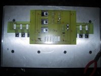
I see you have mounted the FETs at the bottom of the heatsink. I recall seeing a discussion on another thread about how disipation is actually improved by mounting the devices above the mid-line of the heatsink. I can't remember the thread I saw it on but someone else may know of it. (That's old age for you, 40 years old this weekend, and the brain cells are dying at ever increasing rate - but I find the red wine makes it bearable.)
Behemoth comes to mind with those dimensions. Enjoy the end result.
Paul
Where's the corkscrew gone?
Hi SuppersReady,
Actually the 12 mosfet were mounted at the center of the aluminium plate, attached to 4pcs 135 X 125 X 300mm heatsink and tight them together using 8 X M8 screw.
I was intentionally mount the Mosfet upside down to minimize the magnetic induction created by the 2 power toroidal and 4 inductors which I intend to mount them at the bottom of the chasiss.
About the screw head hole was using 14mm End Mill drill to 8mm depth, make it look like flat at the surface of the alu. plate.
Attachments
Hi Alexmark,
To address your original post, I don’t know the down side of stacking the toroidal transformers. I would have thought as you have, that the mutual inductance would be a problem.
Ideally, mutual inductance is minimized by, first distance, but I’m assuming this is not an option. If they must be mounted in proximity to each other, then they should be mounted at right angles. One can be placed flat against the front panel and the other would then be placed as it is in your photo. This would set them at right angles with mutual inductance minimized.
This said, I’ve seen plenty of projects on this site that ignore this property completely, stacking the transformers on the same center, and they don’t seen to be having any problems. At least none that have been talked about to my knowledge.
I think I would take the gamble and stack the transformers on center to save the space. Maybe one of the guys that have done this will chime in and let us know how it turned out, but suspect it’s not a problem.
Just my thoughts,
Rodd Yamas***a
All the info regarding stacking toroids is here:😉 http://www.diyaudio.com/forums/showthread.php?s=&threadid=5771&highlight=stacking+toroids
Hi Alexmark,
Perspective playing tricks, must look closer next time. I was right about the brain cells!
Cheers
Paul
Perspective playing tricks, must look closer next time. I was right about the brain cells!
Cheers
Paul
- Status
- Not open for further replies.
- Home
- Amplifiers
- Pass Labs
- Help on Power supply layout.!