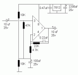
With the help of sr. members I have developed preamp (attached file) but I could not make 100% noise free or clean sounding. Sometimes I see the speaker's cone movement is not matching to music strock. Overall some correction is required to my attached circuit. Please help me.
Thank you.
Thank you.
Attachments
In Your Circuit diagram pin 4 is not connected to ground.
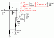
Also add some local decoupling to the op amp. A 100 uf 16v bi-passed with a 0.1 mkt will help the sonic performance and keep things stable.
Also add some local decoupling to the op amp. A 100 uf 16v bi-passed with a 0.1 mkt will help the sonic performance and keep things stable.
Hi, pra3718,
please help us with a more precise description.
Could the cone movements be very low frequent music signals that the speaker reproduces below the listening threshold? http://en.wikipedia.org/wiki/Equal-loudness_contour
The noise you have is hum, right? Use the search function. There are many threads dealing with that, because there are many possible sources for hum, e. g. inductive coupling from the transformer, ground loops, bad solder joints, to name just a few.http://sound.westhost.com/troubleshooting.htm#earth
Thank you.
Your approval is needed. Pl find my altered schematic. Alteration is in RED colour.
Prior to addition of Cap 0.22uf on Pin 1-2, there was SSSSSSSS type of sound. for this type of sound I have to open mouth & SSSSSSS. Cap 0.22uf on Pin 1-2 is removed this SSSSSS.
Now if I shut the mouth & sound by my nose like HAMMMMMMM yes, this type of sound is present now. I thought this HAMMM is comming from my source(DVD Player) but not I tried with remove all connection with DVD Player. One more thing if I touch the Subsoofer with no sound I can feel the vibration/hammm.
Pacificblue, another question is you know my PSU right? For Preamp I am using IC:7812 (regulated) If I add IC:7812 to PSU and if common supply <regulated supply> to all TDA1554q & NE5532 so is that HARM ?
Thank you & Regards.
Attachments
There is a joint between the supply midpoint generator (2x10K) and the top of Ci (100uF near the inverting input). Since you have not labelled the parts I find it exceedingly difficult to point it out to you.
The connection needs to be broken, as it is feeding half the supply voltage to the inverting input through the feedback resistor network and may be a source of hum. I've made this remark on your earlier thread but it is still not corrected.
Unless, of course, it's a mistake in the drawing.
The connection needs to be broken, as it is feeding half the supply voltage to the inverting input through the feedback resistor network and may be a source of hum. I've made this remark on your earlier thread but it is still not corrected.
Unless, of course, it's a mistake in the drawing.
Sorry, I could not understand you sangram. Why don't you download my schematic, ALTER it & post it again. Can you do it for me.
Thank you & Regards.
Thank you & Regards.
Why do you need a preamp with a gain of ~4 between a DVD player and amplifier??
It sounds to me as if you have too much gain hence hum and hiss.
The capacitor 0.22uF is acting as a top cut and will result in muffled sound.
Where is the volume control?? Before or after the preamp?
Andy
It sounds to me as if you have too much gain hence hum and hiss.
The capacitor 0.22uF is acting as a top cut and will result in muffled sound.
Where is the volume control?? Before or after the preamp?
Andy
@Poynton - he's using it for a subwoofer amp, hence cutoff is not an issue. However the sub must be much more inefficient than the rest of his satellites, needing the higher gain.
@pra - I will defer the help till tomorrow evening, if someone else can do it great. I'm posting from a phone now. Impossible for me.
@pra - I will defer the help till tomorrow evening, if someone else can do it great. I'm posting from a phone now. Impossible for me.
1) The 7812 regulator should be replaced by an LM317 adjustable regulator. Decouple the "Adjust" pin with a good quality 1uF film capacitor (or a 10uF electrolytic). This will dramatically reduce the noise at the artificial ground node on the non-inverting input. Bob Pease at National Semi wrote an entire white paper on the bypass for these regulators.
2) Consider reducing the values of the gain and feedback resistors. If your CD player can stomach it, use 22K.
2) Consider reducing the values of the gain and feedback resistors. If your CD player can stomach it, use 22K.
The 100 µF capacitor must only be connected to the 4.7 k resistor, not to anything else. In your schematic there is a connection also to the two 10 k and the 47 k resistors, which you have to interrupt.pra3718 said:Sorry, I could not understand you sangram.
Noise at that level is not an issue with this setup. It is based on a multi-channel car radio TDA.jackinnj said:1) The 7812 regulator should be replaced by an LM317 adjustable regulator. Decouple the "Adjust" pin with a good quality 1uF film capacitor (or a 10uF electrolytic). This will dramatically reduce the noise at the artificial ground node on the non-inverting input. Bob Pease at National Semi wrote an entire white paper on the bypass for these regulators.
2) Consider reducing the values of the gain and feedback resistors. If your CD player can stomach it, use 22K.
The 100 µF capacitor must only be connected to the 4.7 k resistor, not to anything else. In your schematic there is a connection also to the two 10 k and the 47 k resistors, which you have to interrupt.
As per my experiment, 100 µF capacitor should not disconnect from 10K+10K+47K joint. I removed the joint 4.7 K and add 2.2 µF 25V capacitor to 4.7K to Ground. Now subwoofer's sound is stable & Cone movement matching to sound.
It's not a problem but some improvements is required in my NE5532 preamp very low frequency I want to cutt-off.
Today I experienced NEW PROBLEM. I can not RUN my system when CEILING FAN is On.
In fact, everything was sounding good from last 30 min. I powered on CEILING FAN after 10 Sec. all speaker sounding like PAT-PAT-PAT-PAT-PAT-PAT-PAT-PAT.... immediately I switched off CEILING FAN & found PAT-PAT sound is off from system. I do not understand the combination between my SYSTEM & CEILING FAN.
Thanks & Regards.
That is exactly what you should have done, the circuit is fine now. The 100uF will stabilise the half-bias point and the 2.2uF (I would use a little higher - 22uF is fine) will keep the DC gain at 1.
The fan problem is a ground loop or EMI. I suspect (as I have all along) that you have some layout issues. Unfortunately can't help as I've not seen the layout. Try putting a small (~100pF) capacitor between pin 2 and 3 of the NE5532, it may help. Also try runnin the amp from a different wall socket.
As jackinnj says, reduce the value of the .22uF cap, 220pF would be a good value for you as you obviously have a lot of crud at the output.
The fan problem is a ground loop or EMI. I suspect (as I have all along) that you have some layout issues. Unfortunately can't help as I've not seen the layout. Try putting a small (~100pF) capacitor between pin 2 and 3 of the NE5532, it may help. Also try runnin the amp from a different wall socket
NE5532 preamp is used for subwoofer only. No preamp is used for satellites, this type of SOUND come from sub+satellites.(all speakers)
Running my amp from different wall socket.
Thanks
sangram said:
As jackinnj says, reduce the value of the .22uF cap, 220pF would be a good value for you as you obviously have a lot of crud at the output.
0.22uF is in there to sub-woofitize the opamp, problem is that above a few hundred hertz it looks like a short across the feedback resistor and you just have a buffer, so the gain is 0dB out to infinity. 220pF will start to roll off at 15kHz and will be down 3dB at 33kHz.
You can easily make a 2 pole Sallen-Key low pass filter for a sub -- get the FilterPro software from Texas Instruments (it's free), select Sallen-Key, 200Hz, and gain of 5.6 (15dB).
sub-woofitize
😱 😀
@Pra: Use a passive filter at the input - .47uF to ground and 3.3K in series, to cut high frequencies above 100Hz, or the sub will basically be playing through all the music range, just a little higher in bass but also trying to play all the sound. You need to cut the sound before it gets to the chip (I haven't spoken like this in a while 🙂)
I don't have a suggestion for you on the clicking, it is some interference with your power supply. I'm out of ideas, but maybe someone here can help.
subwoofer filter
hi sangran
use subwoofer active filter from efy very easy circuit
to assemble for regulated 15volts use power supply circuit of of
electronics australia studio preamplifier uses lm317 t and lm337 t
both have pcb paterrns
andrew lebon
hi sangran
use subwoofer active filter from efy very easy circuit
to assemble for regulated 15volts use power supply circuit of of
electronics australia studio preamplifier uses lm317 t and lm337 t
both have pcb paterrns
andrew lebon
sangram said:
😱 😀
@Pra: Use a passive filter at the input - .47uF to ground and 3.3K in series
otherwise known as a 1-pole filter...nothing wrong with that...
here in the new york area we regularly convert nouns to verbs...it's the new, new lingua franca.
Re: subwoofer filter
Thanks. I don't need one now, but if I ever decide to build a subwoofer, I'll look it up! btw it's sangram, thanks!
Nounerbing, eh? Or verbouning? Looks like someone write a book on that.
andrewlebon said:hi sangran
use subwoofer active filter from efy very easy circuit
to assemble for regulated 15volts use power supply circuit of of
electronics australia studio preamplifier uses lm317 t and lm337 t
both have pcb paterrns
andrew lebon
Thanks. I don't need one now, but if I ever decide to build a subwoofer, I'll look it up! btw it's sangram, thanks!
here in the new york area we regularly convert nouns to verbs...it's the new, new lingua franca
Nounerbing, eh? Or verbouning? Looks like someone write a book on that.
I don't have a suggestion for you on the clicking, it is some interference with your power supply. I'm out of ideas, but maybe someone here can help
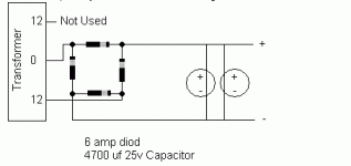
1) Please find my power supply as attached picture file
2) Amplifier is TDA1554q (It is as per Philips datasheet accept input caps are 10 uf 25v)
3) Preamp NE5532 for sub. (You know the Circuit)
Thanks
Attachments
- Status
- Not open for further replies.
- Home
- Amplifiers
- Chip Amps
- Help on NE5532 preamp Noise FREE


