PCB
Hi,
I am going to order few PCbs for this amp.Please let me know if anyone wants a PCB.
Regards,
Sachin
Hi,
I am going to order few PCbs for this amp.Please let me know if anyone wants a PCB.
Regards,
Sachin
Well guys, i just tested the boards on a stereo setup and work like charm, rly quiet and no distortion or hummmm sound.
Ty guys for help me to make this pcb.
Cheers
Ty guys for help me to make this pcb.
Cheers
Use the "ratsnest" button, or simply type "r" (then return) in Eagle's command line.
You can specify if ratsnest processes polygons or not :
"set poly on"
"set poly off"
in the commandline, again (and without ")
Once a polygon have been rendered, there is no easy way to turn it off again, but there are workarounds :
a) drag one edge a bit away, then back again, then refresh display (zoom out, etc).
c) close the .BRD only and the open it again from the schematic editor. DO save changes if prompted so, otherwise board and schematic will be inconsistent and will stop being updated synchronuously (the so-called back-annotation).
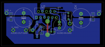
Sorry to revive a dead thread 😱 but the title is just fitting and I used one of the layouts posted here as reference.
I took the necrofago's layout (the one edited by quadtech) and tried my little best to modify it into a version without SMDs.
This is the result - any comments?
I took the necrofago's layout (the one edited by quadtech) and tried my little best to modify it into a version without SMDs.
This is the result - any comments?
Attachments
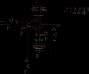
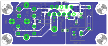
R3 is too far away from R1 and R2. = too big a loop area in the input wiring.
The trace from input terminal pin2 to C1 should be UNDER C1 to minimise loop area.
Can you locate c5,6,10& 11 much closer to power pins. At least one cap at each power pin.
I don't know what type of current pulses flow into pin5, but hardly anyone adds HF decoupling to this pin
Why does it get ignored?
Do they know something about the pin5 current flow that I have not seen reported?
I don't like C2 tied into pin9.
Read about stability and decide whether a Pin9 capacitor will help or hinder stability.
Instead I tie C2 to Signal Return alongside R2.
C3 and Cz are too low value.
Redraw your sch input with real traces joining all the Signal Grounds, move C3 to tie into the bottom of R2. Then your input looks more like what it is, a differential input stage.
Last edited:
I have seen recommendations from 0r0 to 22r
Most adopt 10r
Read Leach's Lo Tim.
Thanks andrew, thats clear up my doubt.
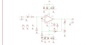
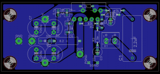
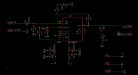
Also recently I have build a LM3886 pcb, but the is slight problem with the build. There is a very low HUM(no white noise) if i put my ear very near to speaker, this is the circuit and PCB, any help is appreciated, only one ground wire is connected to ground in pcb from star center point. Input, output and power ground is connected directly to star ground and the star ground is connected to main earth with 1ohm resistor
Attachments
- Status
- Not open for further replies.
- Home
- Amplifiers
- Chip Amps
- Help on LM3886 PCB Routing