Hai,Its Benjamin
I have my grandfathers valve amp EL84 push pull,
Cooper Smith amp. I would like to convert the 5V4 tube rectifire,to a solid state rectifire.I need your help on selecting the value of capacitor,and how to overcome the voltege spike
PS.can you supply a schematic with the value of the parts
Your help will be appreciated
Attachments
Last edited:
have you try to use PSDII?
it is a great tool for designing power supplies.
with SS diode the caps can be allot higher in capacitance than with tubes, so if it was me i would just get 40uf+40uf 600v for the CLCL.
it is a great tool for designing power supplies.
with SS diode the caps can be allot higher in capacitance than with tubes, so if it was me i would just get 40uf+40uf 600v for the CLCL.
well the simplest way is to plug in a yellow jacket type YJR and replace c9 and c10 with a 32uf/32uf 500V cap
when you say VOLTAGE SPIKE, do you mean that solid state rectifier doesnt have the slow warm up as the 5v4? or do you mean with SS you will get a slight higher voltage on B+?
when you change from tube to ss your B+ will be a little higher, so you need to adjust your cathode current to compensate for the higher B+ so your el84 doesn't over dissipate.
An appropriate resistor in series with the solid state rectifier would bring B+ back down to where it should be, and make life easier for the transformer. A higher cap value for C9 (as others have suggested) makes life harder for the transformer.
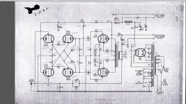
BTW, looks like there's a mistake on the schematic - no resistors from V1's grids to ground.
BTW, looks like there's a mistake on the schematic - no resistors from V1's grids to ground.
Hai,Its Benjamin
I have my grandfathers valve amp EL84 push pull,
Cooper Smith amp. I would like to convert the 5V4 tube rectifire,to a solid state rectifire.I need your help on selecting the value of capacitor,and how to overcome the voltege spike
PS.can you supply a schematic with the value of the parts
Your help will be appreciated
What is the reason for eliminating the vacuum rectifier? As much as 20 years of service can be obtained from a Mullard GZ32/5V4. 😉 If the high price of NOS is more than you can bear, install a Chinese 5AR4. Make C10 47 μF./450 WVDC. "Play" with the value of C9, starting with 1.5 μF. Increase the value of C9, slowly, until you measure 300 VDC at C10.
well the simplest way is to plug in a yellow jacket type YJR and replace c9 and c10 with a 32uf/32uf 500V cap
What is a "Yellow plug"
And wont the large value cap will bring the voltege over 300V??
Take it easy on me I am only 14 years old😉
a "yellow jacket" is brand name of a solid state replacement for tube rectifier. in it has the diodes and some resistors packaged in a plug in module.
Solid State Tube Rectifier, Yellow Jackets® | Antique Electronic Supply
the voltage rating of the cap means it will operate safely up to 500V. When you so solid state with the rectifier the B+ is 1.414 times the rms voltage of the secondary until the tubes warm up to the state of conduction (about 425VDC). the 500V cap is for the safety margin in case your using a 110V primary power transformer on 120-125V mains (wall voltage).
a "yellow jacket" is brand name of a solid state replacement for tube rectifier. in it has the diodes and some resistors packaged in a plug in module.
Solid State Tube Rectifier, Yellow Jackets® | Antique Electronic Supply
the voltage rating of the cap means it will operate safely up to 500V. When you so solid state with the rectifier the B+ is 1.414 times the rms voltage of the secondary until the tubes warm up to the state of conduction (about 425VDC). the 500V cap is for the safety margin in case your using a 110V primary power transformer on 120-125V mains (wall voltage).
What about a 240V primary?
Have you download the Duncan power supply simulation that was suggested?
When you do, let us know and we will walk you through it.
It's a very isefull tool for this situation. I will try to draw a schematic for you when I get off work, or someone here can do it before then.
Good luck!
When you do, let us know and we will walk you through it.
It's a very isefull tool for this situation. I will try to draw a schematic for you when I get off work, or someone here can do it before then.
Good luck!
do you know what resistance and the inductance of the choke (L1) is?
it'll help sim the B+ voltage more acurately.
it'll help sim the B+ voltage more acurately.
Yes i have downloaded the Duncan PS simulator,I dont really undersatand how to use it
I don see any votage readous
The specs for the choke is
10H
110ma
200ohm DC resistance
I don see any votage readous
The specs for the choke is
10H
110ma
200ohm DC resistance
Ok, so what you want to do is start with the transformer voltage, Wich is 300v then select fullwave solid state for rectifier after that put I'n your first cap value, I would start at 40uf and then your choke with the resistance and inductance and the second cap 40uf to start with, you can go higher if you like up to 220uf. And for the load, I use the Constance current instead of the resistive load.
As for the current draw of 4 el84 and the input tubes, I would guess its around 160 - 170 ma, so put that I'n as the load of CC. Click SIM to see what B+ you get
As for the current draw of 4 el84 and the input tubes, I would guess its around 160 - 170 ma, so put that I'n as the load of CC. Click SIM to see what B+ you get
- Status
- Not open for further replies.
- Home
- Amplifiers
- Tubes / Valves
- Help Needed ;)