Hi guys
I've recently given my teenage son some of my old AV kit, an AVR, a DVD player, centre and left & right speakers. I was hoping to build 2 small "subs" (this is my first attempt at DIY) for his room from some drivers (6 1/2 Inch) I have laying about, but I need some help... (probably lots of help )
I've been playing around with WinIsd, and it looks like the drivers will "work", but to be honest, I'm really not sure if what I'm doing is correct.
I'm not trying to get super low bass from these drivers, just trying to get a bit more low end (as low as possible) than what the small book shelve speakers are currently playing.
I guess the drivers aren't designed for this application, but this is all I have to work with at the moment.
His room is pretty small, so SPL from the "sub" isn't a major concern.
The amp I have to drive the woofer is rated 50w and 80w continuous power at 8 and 4 Ohms
I was hoping you gents could help me "make them work" for the time being
Please let me know how I can improve on this box size and tuning , and/or if this is an absolute failure of a task
I have the driver in a 40L box tuned at 35hz...
Really appreciate any and all input
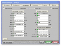
Rated power 50 W
Maximum power 80 W
Nominal impedance Z 8 Ohm
Frequency response fu–8000 Hz
(fu: Lower cut-off frequency depending on cabinet) .
Mean sound pressure level 86 dB (1 W/1 m)
Opening angle (-6 dB) 72°/4000 Hz
Excursion limit +/−10 mm
Resonance frequency fs 36 Hz
Magnetic induction 1,0 T
Magnetic flux 314 µWb
Height of front pole-plate 4 mm
Voice coil diameter 25 mm
Height of winding 12,5 mm
Cutout diameter 148 mm
Net weight 1,1 kg
D.C. resistance Rdc 5,9 Ohm
Mechanical Q factor Qms 2,43
Electrical Q factor Qes 0,66
Total Q factor Qts 0,52
Equivalent volume Vas 38 l
Effective piston area Sd 129 cm²
Dynamically moved mass Mms 13 g
Force factor Bxl 5,4 Tm
Inductance of the voice coil L 1,2 mH
I've recently given my teenage son some of my old AV kit, an AVR, a DVD player, centre and left & right speakers. I was hoping to build 2 small "subs" (this is my first attempt at DIY) for his room from some drivers (6 1/2 Inch) I have laying about, but I need some help... (probably lots of help )
I've been playing around with WinIsd, and it looks like the drivers will "work", but to be honest, I'm really not sure if what I'm doing is correct.
I'm not trying to get super low bass from these drivers, just trying to get a bit more low end (as low as possible) than what the small book shelve speakers are currently playing.
I guess the drivers aren't designed for this application, but this is all I have to work with at the moment.
His room is pretty small, so SPL from the "sub" isn't a major concern.
The amp I have to drive the woofer is rated 50w and 80w continuous power at 8 and 4 Ohms
I was hoping you gents could help me "make them work" for the time being
Please let me know how I can improve on this box size and tuning , and/or if this is an absolute failure of a task
I have the driver in a 40L box tuned at 35hz...
Really appreciate any and all input
Rated power 50 W
Maximum power 80 W
Nominal impedance Z 8 Ohm
Frequency response fu–8000 Hz
(fu: Lower cut-off frequency depending on cabinet) .
Mean sound pressure level 86 dB (1 W/1 m)
Opening angle (-6 dB) 72°/4000 Hz
Excursion limit +/−10 mm
Resonance frequency fs 36 Hz
Magnetic induction 1,0 T
Magnetic flux 314 µWb
Height of front pole-plate 4 mm
Voice coil diameter 25 mm
Height of winding 12,5 mm
Cutout diameter 148 mm
Net weight 1,1 kg
D.C. resistance Rdc 5,9 Ohm
Mechanical Q factor Qms 2,43
Electrical Q factor Qes 0,66
Total Q factor Qts 0,52
Equivalent volume Vas 38 l
Effective piston area Sd 129 cm²
Dynamically moved mass Mms 13 g
Force factor Bxl 5,4 Tm
Inductance of the voice coil L 1,2 mH
Given:
-1- the driver and box are ok (previous post)
-2- you have the drivers
Then I suggest you just do it. Your total exposure is the cost of some wood.
I would not get hung up on fancy boxes or crazy bracing if this is a first for you. They are really second order things.
Have fun!
-1- the driver and box are ok (previous post)
-2- you have the drivers
Then I suggest you just do it. Your total exposure is the cost of some wood.
I would not get hung up on fancy boxes or crazy bracing if this is a first for you. They are really second order things.
Have fun!
Thank you guys
That's great to hear (at least I'm heading in the right direction, so far)
I'm unsure of a few things
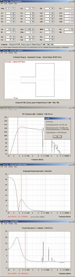
1)what is the colored -3 line indicating (in Transfer function magnitude)
2)the excursion shoots up above the limits when I add any power eg🙁+10watts)
Is this normal? and would I need a high pass filter here?
3)how do I proceed in selecting the correct crossover points for a low pass and high pass filter? (Again I'm not sure if what I'm doing is the correct way)
Using NEO Dan's suggestion of 32Hz tuning, I used for the highpass - 2nd order at 32Hz
This seems about right? It seems to chop off all those high peaks of excursion I mentioned earlier
Not sure about the low pass filter, I've read to use 80Hz or 100Hz??
4) lastly, once I have the crossover points, how do I work out the values of the electronic components? Perhaps some software program?
I guess that's a heck of a lot of questions
Thanks again, I'm very grateful for all the assistance
That's great to hear (at least I'm heading in the right direction, so far)
I'm unsure of a few things
1)what is the colored -3 line indicating (in Transfer function magnitude)
2)the excursion shoots up above the limits when I add any power eg🙁+10watts)
Is this normal? and would I need a high pass filter here?
3)how do I proceed in selecting the correct crossover points for a low pass and high pass filter? (Again I'm not sure if what I'm doing is the correct way)
Using NEO Dan's suggestion of 32Hz tuning, I used for the highpass - 2nd order at 32Hz
This seems about right? It seems to chop off all those high peaks of excursion I mentioned earlier
Not sure about the low pass filter, I've read to use 80Hz or 100Hz??
4) lastly, once I have the crossover points, how do I work out the values of the electronic components? Perhaps some software program?
I guess that's a heck of a lot of questions
Thanks again, I'm very grateful for all the assistance
Thank you guys
That's great to hear (at least I'm heading in the right direction, so far)
I'm unsure of a few things
1)what is the colored -3 line indicating (in Transfer function magnitude)
2)the excursion shoots up above the limits when I add any power eg🙁+10watts)
Is this normal? and would I need a high pass filter here?
3)how do I proceed in selecting the correct crossover points for a low pass and high pass filter? (Again I'm not sure if what I'm doing is the correct way)
Using NEO Dan's suggestion of 32Hz tuning, I used for the highpass - 2nd order at 32Hz
This seems about right? It seems to chop off all those high peaks of excursion I mentioned earlier
Not sure about the low pass filter, I've read to use 80Hz or 100Hz??
4) lastly, once I have the crossover points, how do I work out the values of the electronic components? Perhaps some software program?
I guess that's a heck of a lot of questions
Thanks again, I'm very grateful for all the assistance
Hi RellRaz,
FWIW, I will not answer your Question #1 as I don't think the program you have chosen is capable to give you appropriate answers when the driver has a Qts exceeding 0.5 .
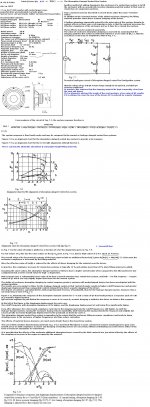
To achieve best performance from your drivers in a ported enclosure:
First,You need a deeper understanding, For example from: Thiele or Here= Small works. Consult the first of submitted pictures.
If you try altering parameters to get a straight flat passband FR(a goal for a reproducer) using a simple program is prejudged to fail because of not being able to include damping behavior of materials in an enclosure/port where the exact dimensions have impact and the physical placement of the port.
Programs that don't include the damping material effects will return like second submitted HR picture: Indication of a broadband bump (more than a critical BW), thus producing colored sound.
Note: HR ( or the simple program you are using) is IMO useful for BR designs only if returning a flat passband for a BR: Then there is no need for using damping materials at all, maybe only a sheet of thin felt covering the rear internal wall.
For your case: A box of 40 L tuned at 27 Hz (Lport=~16”) using a Qts of~0.397 would return a flat FR but your driver would have to use a ~87L volume tuned at ~27 Hz (Lport=~8”) to return an acceptable FR that doesn't have the peak above the passband level or considered being coloring the sound.
This may sound odd but a flat or slightly sloping system response ( even if peaking slightly below ~30 Hz) is not considered to be coloring but a broadband peak of more than a few dB's as seen at the HR simulation sounds IMO very colored.
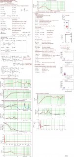
Question #2:You need a >= 18dB HPF to keep excursion down(Who knows the amount of damping your box have?) when the driver show decoupling from the box,a 12 dB filter is not enough.
Question #3: when using only one sub I prefer XO below 80 Hz---> 50-max. 60Hz but if 2 used as stands for the mains I use 80 Hz(min 12dB HPF) or max 120 Hz (min 24 dB/octave HPF) if the sub-drivers is very near the floor level but I never exceed to XO above ~145Hz(24 dB HPF) otherwise.
The third of pictures is using a program MJK:s thats comes very close to predict an speaker box like yours. Zoom the plots as the the damped case(red color) is superimposed on the non-damped(dark-gray).
b
Attachments
- Status
- Not open for further replies.