I have been living a happy life with this preamp since 93, And now I have decided to build a new one with a nice finish instead of the lab looking current one.I will very much want to base it on my old linestage which to my ears is just perfect; But looking at the old pcb, the first thing that comes to mind is decay, loose traces, a lot of repairs etc. It was originally a diy that was shown in a magazine which is no more, So getting the original layout is just not possiple.
After watching these forums for a long time,I have got the impression that laying out pcb`s comes as easy to some of you guys as burbing after drinking a beer But for me it will be a long study of programs to even get near the target. I have changed some semis from smd to thru hole cause my eyes are not what they use to be, and it will make it more flexible for experiments in the future.
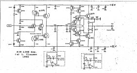
I have got permission from L. Clausen to post the schematic here.
Hope that one of you guys will swallow the bate.
Regards.
(Sorry for my rusty english)😱
After watching these forums for a long time,I have got the impression that laying out pcb`s comes as easy to some of you guys as burbing after drinking a beer
But for me it will be a long study of programs to even get near the target. I have changed some semis from smd to thru hole cause my eyes are not what they use to be, and it will make it more flexible for experiments in the future.I have got permission from L. Clausen to post the schematic here.
Hope that one of you guys will swallow the bate.
Regards.
(Sorry for my rusty english)😱
Attachments
How about photographing the old PCB as a starting point.
I know this isn't what you are asking... the two IC's in the diagram called "one point DC servo". Are you sure there isn't an error there. The output of each opamp is shown connected to the low impedance outputs of each main stage... the same point the servo's are shown as sampling via very high value resistors.
I know this isn't what you are asking... the two IC's in the diagram called "one point DC servo". Are you sure there isn't an error there. The output of each opamp is shown connected to the low impedance outputs of each main stage... the same point the servo's are shown as sampling via very high value resistors.
it is called One point dc servo. It measures and corrects in the same point.
Works fine by the way🙂
Works fine by the way🙂
The first stage seems to be a transimpedance amplifier, so the "one point servo" will attempt to keep this high-impedance amplifier output dc offset at 0V. I am less certain that the second dc-servo will acomplish the same thing, as the second stage seems to have a low impedance output.
I am less certain that the second dc-servo will acomplish the same thing, as the second stage seems to have a low impedance output.
And the opamp has a 10meg ? series output resistor...
The servo design is a variant of a 'gyrator' circuit, so the effect to to provide a low-impedance load at 0Hz.
Given that the servo functions as a result of a local NFB loop, I'd be wary of saying that there's no feedback loops in the design 🙂
Given that the servo functions as a result of a local NFB loop, I'd be wary of saying that there's no feedback loops in the design 🙂
Doh!
I of course meant to say that the first stage was a transCONDUCTANCE amplifier! (current out for voltage in).
I of course meant to say that the first stage was a transCONDUCTANCE amplifier! (current out for voltage in).
It has worked and been in use daily since 93
I'm sure it has... it's just that the servo operation (particularly the second one) doesn't look correct.
We are going off your original question here.
Can you not just copy the original PCB layout to reverse engineer another?
😕the original pcb is one big integrated unit incl. Riia powersupply relays etc. so not easy.
I have tryed.
I have tryed.
 Still hoping

- Status
- Not open for further replies.
- Home
- Source & Line
- Analog Line Level
- Help needed with pcb design!