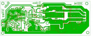
I'm building amp based on iraudamp7d reference design. I made new PCB layout, but almost same as iraudamp7d. Today I soldered it to the stage, to just test the irs2092. No output mosfets, no OCP. Only thing I managed to do is kill the irs2092. On the both output is -40V. Could someone check the PCB?
What should I check? I have a osciloscope to.
Does anyone have a tested simple as possible PCB that I could try?
What should I check? I have a osciloscope to.
Does anyone have a tested simple as possible PCB that I could try?
Attachments
All you can do is go back and check your schematic for errors.
Personally I wouldnt have powered it up without the mosfets.
The amp requires feedback to oscillate.
Personally I wouldnt have powered it up without the mosfets.
The amp requires feedback to oscillate.
why didn't you use fets? you can solder everything on, and just don't connect main voltage... you can provide +/-5 for the IRS and about 12v for IRS gate drive
And if that all is good, you can use main voltage... you can even ramp it up slowly from +/-0v to +/- what even you have for your supply, it you can get your hands on adjustable supply, not some trafo or smps
I would never not use fets when powering up IRS
And if that all is good, you can use main voltage... you can even ramp it up slowly from +/-0v to +/- what even you have for your supply, it you can get your hands on adjustable supply, not some trafo or smps
I would never not use fets when powering up IRS
- Status
- Not open for further replies.