I guess it might be worth mentioning this as well - be careful of confusing ZTX and BC, especially with the '550' part.
Q2 should be ZTX550 or BC560 (but not BC550)
Q3/Q4 should be ZTX450 or BC550 (not ZTX550)

Fingers crossed. Hope this resolves for you soon!
Cheers,
Stephen
Q2 should be ZTX550 or BC560 (but not BC550)
Q3/Q4 should be ZTX450 or BC550 (not ZTX550)
Fingers crossed. Hope this resolves for you soon!
Cheers,
Stephen
I just checked an they are indeed ZTX. Swore I ordered the Fairchild ones. I will switch them around....
Thank you. Will report back.
Most likely you ordered the Zetex (ZTX) parts because BC560C is no longer available at Mouser or Digikey

That's a really learning curve for me. Feeling really satisfied in completing that challenge. What a great forum this is.
Congratulations! Enjoy the amp, it's definitely one of the great ones and the satisfaction of having brought one to life!
Hi Again,
I am wondering how silent the Aleph J should be in normal operation?
I am measuring about 3.5Mv AC on both speaker terminals with the amplifier connected and about 5.1 with the RCA plugs out.
I have checked for earth loops and I don't have any; 0V is elevated above ground by 10R using the CL-50 NTC and this is what I measure between IN- and the case.
I have moved all the cables about and put them right next to the AC cable but the measurements don't change.
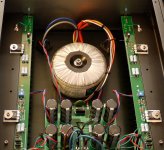
I do wonder if the proximity of the boards to the transformers could be an issue. Please see the photo above. I can replace with a single toroidal but before I spend and money or start taking the case apart is this likely the cause?
Graham
I am wondering how silent the Aleph J should be in normal operation?
I am measuring about 3.5Mv AC on both speaker terminals with the amplifier connected and about 5.1 with the RCA plugs out.
I have checked for earth loops and I don't have any; 0V is elevated above ground by 10R using the CL-50 NTC and this is what I measure between IN- and the case.
I have moved all the cables about and put them right next to the AC cable but the measurements don't change.
I do wonder if the proximity of the boards to the transformers could be an issue. Please see the photo above. I can replace with a single toroidal but before I spend and money or start taking the case apart is this likely the cause?
Graham
Solder in links between board halves (marked in blue circle), and report back.
If that is allready done, try gathering all gnd wires to one side of the PSU pcb, as close to each other as possible.
What is that black wire connected to gnd in the front of the pcb?
I think it is also wise to include several pics of the whole amp from different angles.
Also, your untwisted DC wires are asking for hum. They are also routed high. Not ideal.
This is especially important for the wires from you bridges to your psu pcb. They include raw ripple filled DC. 5mV at the terminals is no surprise.
GND bridges between two halves of cap bank pcb, how you arrange them?
I believe only that one on output side must be installed, that on input side left open
I believe only that one on output side must be installed, that on input side left open
It looks like he installed one link, at the back. He could link all the four points at the back, for as low impedance across the junction as possible. I agree in dropping links at the ripple filled front of the PCB, though in actual tests on my BA-3 I measured no difference when removing the front links.GND bridges between two halves of cap bank pcb, how you arrange them?
I believe only that one on output side must be installed, that on input side left open
It looks like he installed one link, at the back. He could link all the four points at the back, for as low impedance across the junction as possible. I agree in dropping links at the ripple filled front of the PCB, though in actual tests on my BA-3 I measured no difference when removing the front links.
Thanks I will try your suggestions and post some more pics in the nezt few days.
The black lead at the front of the PCB and the red to the left of the picture is to the speaker protection.
As pointed out I linked the two halves at the front of the PCB. I will experiment with that.
Thanka
The black lead at the front of the PCB and the red to the left of the picture is to the speaker protection.
As pointed out I linked the two halves at the front of the PCB. I will experiment with that.
Thanka
Not sure about those speaker protection connections, but they are at speaker return gnd potential, you need to gather them with all the other audio gnd connections at one single point (euroblock) at the output side of the psu.Thanks I will try your suggestions and post some more pics in the nezt few days.
The black lead at the front of the PCB and the red to the left of the picture is to the speaker protection.
As pointed out I linked the two halves at the front of the PCB. I will experiment with that.
Thanka
Also, did you use a thermistor to isolate audio gnd from chassis/safety gnd? Do this too if not. And do not mix this connection into the same euroblock as the other gnd wires.
Good luck!
Regards,
Andy
I have:
(1) Removed the connection at input side, between the two halves of the PS board input but leaving the connection at the output side of the board. This connection uses thick copper wire.
(2) Taken all of the 0v output from the PS from the same block on the right hand side of the output board, including the NTC to GND.
(3) Twisted the red and black wires from the bridge rectifiers to the input of the PS board.
(4) Changed the layout to allow the transformers to be moved to the centre of the mounting plate and, as far as possible, away from the amplifier boards.
(5) Rerouted the mains AC underneath the mounting plate.
(6) Made the earth ground connection close to the IEC.
(7) Altered the power for the protection board to take from the output of the PS board, using GND and +Ve
So it is interesting because it measures the same but sounds obviously quieter. In fact its pretty acceptable, but I still would like to get to the bottom of the AC on the output. I am measuring
5.1mv with the cables out.
3.4mv with the input RCAs shorted.
I do not have a scope to measure the ripple but I have a friend who has one and can measure it for me. What is an acceptable value of the ripple from the PSU please? Should I measure 0 to +ve, 0 to -ve and +ve to -ve.
(I know I have the NTC removed in this picture. I was measuring the 0v to GND with it out. I had a reading of 88.1K but I am not sure if that was simply the lack of an earth reference giving a spurious meter reading)

Pic attached, thanks.
(1) Removed the connection at input side, between the two halves of the PS board input but leaving the connection at the output side of the board. This connection uses thick copper wire.
(2) Taken all of the 0v output from the PS from the same block on the right hand side of the output board, including the NTC to GND.
(3) Twisted the red and black wires from the bridge rectifiers to the input of the PS board.
(4) Changed the layout to allow the transformers to be moved to the centre of the mounting plate and, as far as possible, away from the amplifier boards.
(5) Rerouted the mains AC underneath the mounting plate.
(6) Made the earth ground connection close to the IEC.
(7) Altered the power for the protection board to take from the output of the PS board, using GND and +Ve
So it is interesting because it measures the same but sounds obviously quieter. In fact its pretty acceptable, but I still would like to get to the bottom of the AC on the output. I am measuring
5.1mv with the cables out.
3.4mv with the input RCAs shorted.
I do not have a scope to measure the ripple but I have a friend who has one and can measure it for me. What is an acceptable value of the ripple from the PSU please? Should I measure 0 to +ve, 0 to -ve and +ve to -ve.
(I know I have the NTC removed in this picture. I was measuring the 0v to GND with it out. I had a reading of 88.1K but I am not sure if that was simply the lack of an earth reference giving a spurious meter reading)
Pic attached, thanks.
Last edited:
I have not been following thread closely but are all grounds, both audio boards, connected to one PS ground. That is input and output grounds from both audio boards to just one PS ground. That and be sure and run wire from the one spot PS ground to the IEC earth ground as well. What you are measuring is what I saw without the PS ground to IEC ground wire. Hooking input and output grounds to audio boards works for some but never for me. Star ground is best and works.
Just some "if it were me" observations.. I would probably focus on one channel at a time. Power just the one channel, inputs shorted, test, troubleshoot, fix. Then other channel by itself. Then both together. I like layouts that get those rectifiers and associated big nasty current spikes away from stuff, like NP does in his factory J2 and many others. And I dislike these amplifier boards that have the pos and neg rail connection a mile apart. I like a nice twist all the way to pcb with those connections... together, sigh. Rotating the toroid could help. Turn it while listening and see if you can find a sweet spot that gives the lowest noise. I take speaker (-) to the starground, not the amp board. You still need a ground wire to the amp board for housekeeping, but that's not much current. A 10 ohm ground lift resistor could be helpful there. I have a CL-60 between starground and chassis ground like most people. Measure resistance to verify. I don't use speaker protection, but it's another thing to verify, bypass, troubleshoot, etc. to eliminate as a potential cause.. or not. Beyond that.. maybe CLC instead of CRC. And / or more capacitance. I'm still using a cap multiplier in my monoblocks after all these years. I want to try a CLC at some point though.
Attachments
- Home
- Amplifiers
- Pass Labs
- Help needed with AlephJ build