Hello. It will be long story, so grab some coffee. I have been passionate audio lover since early age. I used to build some speakers, unfortunately, most of design went into choosing drivers and modeling the box. My last speakers with Peerless SDS 164 and Visaton DT94 was built maybe 15 years ago. I did not had much of experience with crossover design, so went easiest route. First order filters. I have decided to upgrade filters, but would like to get some help.
Speakers with initial crossover network
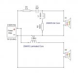
Crossover network: https://photos.app.goo.gl/aKRwSKLawVfjps5G9
Near field response, center of tweeter: https://photos.app.goo.gl/sRQStnVDSnhziwM48
Frequency response in listening position (sofa, untreated room): https://photos.app.goo.gl/njk6CFUZZexbhMhPA
Near field frequency response of high frequency driver, with filter: https://photos.app.goo.gl/HfYwCZ8WBtvqzAYW9
Near field frequency response of mid-bass driver, with filter: https://photos.app.goo.gl/VJ55tVNrgGMH1N8S6
Port response: https://photos.app.goo.gl/4TqmxnUDEMxkpa2M9
As starting point, I have decided to lover tweeter sensitivity and drive it out of phase. Simulation looked promising.
https://photos.app.goo.gl/Qy6kvAy4ka2shtXc8
Unfortunately, if simulation and measurements of speaker before making changes to crossover correlated quite well, now correlation is gone.
Near field response, center of tweeter: https://photos.app.goo.gl/2BpapAb5KEFyodfM7
Comparison before and after. Green after changes, teal before changes: https://photos.app.goo.gl/8Ad2q99bf8ttGe4c7
I would like to get some advices for designing crossover for these drivers. Stay first order? How to deal with hole around 2k? Any idea what could cause dip in 70Hz. It seems it is not caused by the room, because it is present in nearfield measurements.
Speakers with initial crossover network
Crossover network: https://photos.app.goo.gl/aKRwSKLawVfjps5G9
Near field response, center of tweeter: https://photos.app.goo.gl/sRQStnVDSnhziwM48
Frequency response in listening position (sofa, untreated room): https://photos.app.goo.gl/njk6CFUZZexbhMhPA
Near field frequency response of high frequency driver, with filter: https://photos.app.goo.gl/HfYwCZ8WBtvqzAYW9
Near field frequency response of mid-bass driver, with filter: https://photos.app.goo.gl/VJ55tVNrgGMH1N8S6
Port response: https://photos.app.goo.gl/4TqmxnUDEMxkpa2M9
As starting point, I have decided to lover tweeter sensitivity and drive it out of phase. Simulation looked promising.
https://photos.app.goo.gl/Qy6kvAy4ka2shtXc8
Unfortunately, if simulation and measurements of speaker before making changes to crossover correlated quite well, now correlation is gone.
Near field response, center of tweeter: https://photos.app.goo.gl/2BpapAb5KEFyodfM7
Comparison before and after. Green after changes, teal before changes: https://photos.app.goo.gl/8Ad2q99bf8ttGe4c7
I would like to get some advices for designing crossover for these drivers. Stay first order? How to deal with hole around 2k? Any idea what could cause dip in 70Hz. It seems it is not caused by the room, because it is present in nearfield measurements.
Have you timed the measurements you used in the simulator?
You could try crossing your woofer closer to 2kHz and lifting there and cutting above.
You could try crossing your woofer closer to 2kHz and lifting there and cutting above.
We'll need the external dimensions of the box + baffle layout.
By 'nearfield', how nearfield which is considered to be < ~1/4" (6.35 mm)?
By 'nearfield', how nearfield which is considered to be < ~1/4" (6.35 mm)?
Last edited by a moderator:

By definition, it was far from nearfield, 5-8cm away from the driver.
Baffle layout:
Front: 101,5x20 cm (40x7,9 in)
Tweeter center 7,5 cm from the top (3in)
Mid-bass 22cm from the top (8,5in)
Port size, 8cm wide, 11,5cm long 12,5cm from bottom (3,14in x 4,5in, 5in from bottom)
Internal volume 27 liters 0,95 cubic feet
Baffle layout:
Front: 101,5x20 cm (40x7,9 in)
Tweeter center 7,5 cm from the top (3in)
Mid-bass 22cm from the top (8,5in)
Port size, 8cm wide, 11,5cm long 12,5cm from bottom (3,14in x 4,5in, 5in from bottom)
Internal volume 27 liters 0,95 cubic feet
Re:'Stay first order?' - absolutely not - 2nd order on the woofer, 3rd order reverse phase on the tweeter. The tweeter isn't a good match for that woofer, consider a tweeter with a lower Fs
Re:'How to deal with hole around 2k?' - try reversing the phase of the tweeter
Re:'How to deal with hole around 2k?' - try reversing the phase of the tweeter
Geoff's remark got me taking a harder look at the woofer's scaled drawing Vs picture, so FWIW, revising the polar matching XO point = ~2184 Hz based on published specs of the dust cap's ~ diameter Vs the VC's, so now we have both accurate enough technical theory and 'hands on' confirmation. 😉
Firstly - where are you getting your frequency responses from? If you have simply traced these from the manufacture curve - which is done on an infinite (well IEC) baffle, then you are missing baffle step rise. basically your bass response will be much lower than the graphs you have. This is also indicated by the small woofer inductor. This driver will want at least a 1.8mH inductor or it will sound lean / thin (asuming you are using this in room and not as an in bookshelf / nearfield / desktop pair of speakers).
With an ~ 89dB sensitive woofer, you will want to be aiming for an 85dB net system response, or you will "lack bass".
You will also likely need a parallel capacitor on the woofer to remove the breakup node ~ 5Khz. if you "lose too much" output with a capacitor, you can put a series resistor in with the capacitor to reduce the "order". If you still lose too much woofer output, add an inductor to the cap - resistor leg to create a series notch. short the resistor in the circuit (or make 0.1 ohms) and tune capacitor / inductor value until you hit the breakup (e.g. 5KHz) then increase resistance to reduce the Q of the notch to hit your target acoustic slope.
Secondly, if you traced the curves from the peerless data sheet - I think you've "shifted left" an octave by mistake.
If you are unable to measure - then you will at least need to apply through software baffle step and diffraction ripple to the manufacturer curves to provide a more sensible set of data.
Last edited:
Yesterday I have treated boxes with sintepon, I hope it help to reduce standing waves in box.
1 meter response, not gated https://photos.app.goo.gl/YUovxDv7Y866zf6o9
1 meter response gated https://photos.app.goo.gl/ipHAwAvB5Raf5yuD8
I have tried simulate tuantran solution, but it did not seem to be promising, or I am missing something
https://photos.app.goo.gl/fVYgvRBhMtfw8esJ9
1 meter response, not gated https://photos.app.goo.gl/YUovxDv7Y866zf6o9
1 meter response gated https://photos.app.goo.gl/ipHAwAvB5Raf5yuD8
I have tried simulate tuantran solution, but it did not seem to be promising, or I am missing something
https://photos.app.goo.gl/fVYgvRBhMtfw8esJ9
Apart from the sub-optimal crossover it seems quite ok to me. If you want to check the internal damping, do 2 things:
- Measure impedance with a slow sweep or stepped sine, resonances will show like spikes
- Measure the woofer close range, about 1cm from the cone and make a CSD plot or burst decay plot. I prefer the latter. Resonances will show like ridges.
I was trying to make some calculations for 2'nd order filter. As starting point I have used online calculators and Vituix CAD software.
I have used this example. It should be Linkwitz riley, but using this tool it shows as Chebychev alignment, so I am little bit confused. On other hand simulation looks quite good. Could someone suggest solution how to filter out woofer's 5khz peak? What is "normal" workflow designing filters?
I have used this example. It should be Linkwitz riley, but using this tool it shows as Chebychev alignment, so I am little bit confused. On other hand simulation looks quite good. Could someone suggest solution how to filter out woofer's 5khz peak? What is "normal" workflow designing filters?
I didn't pick it up as I don't know your tweeter, but with a 'resonant frequency' of 1900 Hz, it probably won't like the proposed crossover point, no matter which alignment you use.
I used a very small cap (0.22 or thereabouts) and an 8 or ten ohm resistor across the woofer inductor to kill the woofer peak.
Geoff
I used a very small cap (0.22 or thereabouts) and an 8 or ten ohm resistor across the woofer inductor to kill the woofer peak.
Geoff
When used on a real tweeter compared to an 8 ohm resistor (which a calculator needs to default to), it will be different. If it needs the "apparent" Chebychev filter to be correct then it will be.It should be Linkwitz riley, but using this tool it shows as Chebychev alignment, so I am little bit confused.
It will only be correct on one axis, this is too high a frequency to be using the woofer. Better to cross it down before then... However if you must, try listening off axis and if necessary, use a notch filter which will have a higher Q shape to it.how to filter out woofer's 5khz peak?
- Home
- Loudspeakers
- Multi-Way
- Help needed with 2 way crossover