Please help!
I have two Denon POA-4400 monoblocks. I wish maybe change op-amps,original op-amps are NJM082BD and for XLR-input NJM2068DA.I have LM4562NA op-amps and for xlr-input I have OPA2132P,my question,are my new op-amps better or not?
I have two Denon POA-4400 monoblocks. I wish maybe change op-amps,original op-amps are NJM082BD and for XLR-input NJM2068DA.I have LM4562NA op-amps and for xlr-input I have OPA2132P,my question,are my new op-amps better or not?
Last edited:
Knowing Denon's design, testing house and reputation for quality, I would think that if your op amps were better than theirs, they would have chosen them. In a nutshell, sounds more like fiddling not up grading.
My new op-amps are newer than production of 1989-94 years.Knowing Denon's design, testing house and reputation for quality, I would think that if your op amps were better than theirs, they would have chosen them. In a nutshell, sounds more like fiddling not up grading.
The 082 sounds like a TL082. You need to determine its function before touching that one. Is it for a servo ? If so then the TL082 is perfect.
The LM4562 could be a good swap (imo 🙂) for the 2068.
The LM4562 could be a good swap (imo 🙂) for the 2068.
Take a look here . The power amp is not the POA 4400 but the POA 6600 vicol audio : naim cd5i audio tuning but , I hope ,it can give some ideas..
The NJM082s are run with bootstrapped supplies here, reminds me of certain late-'80s Technics amps (SU-VX800 et.al.). I would leave those well alone unless you really know what you're doing, these circuits are not trivial.
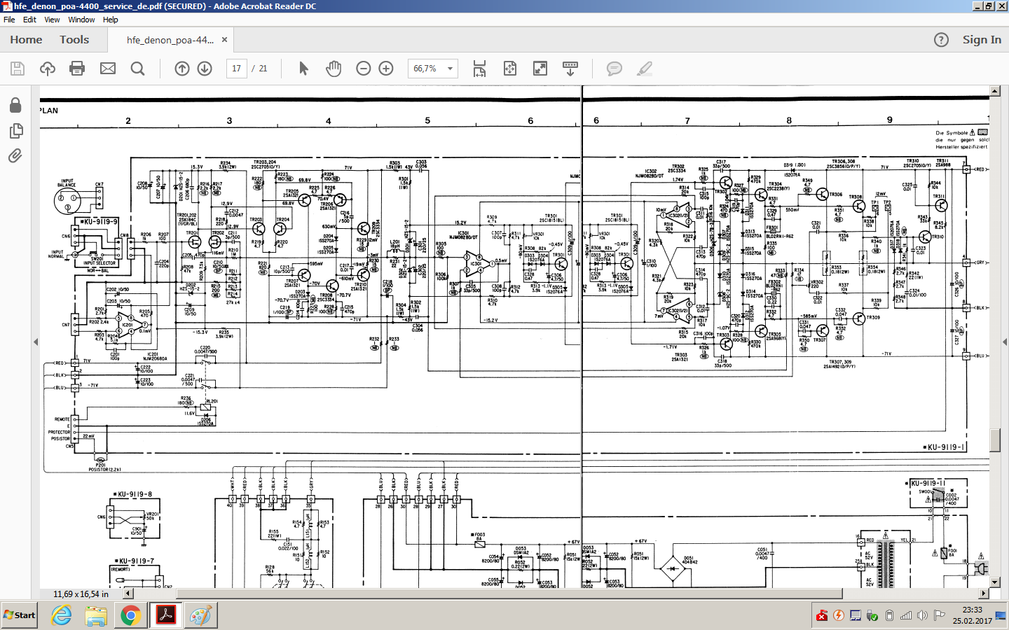
The XLR input has a Big Problem as shown, and it isn't the opamp (though its low noise is sort of wasted here).
Hint: Look at those resistor values.
Noninverting input: 2k4 in series, 2k7 to ground
Inverting input: 4k7 to inverting input node, 5k1 || 100p in feedback.
If that is properly balanced I'm the emperor of China.
Seems to be one of those misguided designs where the designer saw "mismatched" input impedances and "fixed" that - and totally effed up CMRR in the process. (See Balanced Line Receivers, problem #5.)
R203 and R203 must be the same value of (closely matched) resistor, same goes for R201 and R204. And of course, either both of the latter have a cap in parallel (best hand-matched) or none.
Depending on the balanced output this will be run on, I would also consider reducing input gain while you're replacing resistors anyway. Pro output levels can be pretty hot. Looking at a matching pre of the day, the PRA-1500, that guy just adds an inverter for the inverting output and taps off the noninverting as-is, so the XLR actually is 6 dB louder than the unbalanced out. It often is like that.
So maybe 10k on the input vs. 4k7-5k1, or 4k7 to 2k4, or anything in between (6k8/3k3, 8k2/3k9, whatever). Ideally 0.1% MF or hand-matched.
As often the case with these older devices, the XLR input is also afflicted with Pin 1 Problem (same also goes for the matching preamp). Ideally you'd cut the pin 1 connection altogether and run a wire directly from the connector to the chassis next to it. If that gets too messy for some reason, cut the connection from input to circuit ground on the board and find a chassis connection there instead (maybe a standoff if those are metal).
It's not such a big issue here because these things are not mains earth referenced anyway, hence no major currents going over the shield, but still.
Last edited:
This is a great way to kill the amp. Denon made really good stuff but it breaks easily if fools get too close. You're probably not a better designer than Denon so I suggest you leave it alone.
I replaced the NJM 2068 and M5238P with LME 49990 and OPA627 of mine POA 6600a without any problems & issues and now they sound amazing...
- Status
- Not open for further replies.
- Home
- Amplifiers
- Solid State
- Help needed upgrading op-amps Denon POA-4400