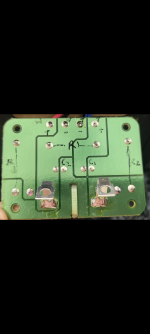
Is that the entire XO? 2 Cs, 3 Rs, 1 L. What does the trace side look like? Where do the wires go?
With only 4 wires evident, i would guess this is the tweeter XO. 3rd order with an L-Pad?
You would need to measure the inductor. You mght have to pull one end out to do that.
dave
With only 4 wires evident, i would guess this is the tweeter XO. 3rd order with an L-Pad?
You would need to measure the inductor. You mght have to pull one end out to do that.
dave
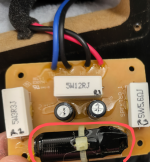
It is the entire crossover, Dave, here seen mounted directly to the speaker input terminal plate:

So the input is direct to the PCB.
So if we need to use these bits to make a 2-way XO, i’d guess 1st order with an L-pad and a <filter> out of the spare C & R. But it could be a zobel on the woofer.
Looks like blue to the tweeter, red to the woofer?
dave
So if we need to use these bits to make a 2-way XO, i’d guess 1st order with an L-pad and a <filter> out of the spare C & R. But it could be a zobel on the woofer.
Looks like blue to the tweeter, red to the woofer?
dave
Last edited:
1st pass: the inductor wasn’t marked on the flip side. L-pad in front of C is a bit strange.

dave
dave
L-pad in front of C is a bit strange.
It looked to me that the HP filter went resistor in series with capacitor then resistor in parallel with tweeter.
P.S. I'll correct your "zonel" to Zobel:

Nicely done, Dave! Perhaps judson1988 will oblige us with the C1 and C2 capacitor values.
P.S. Nominal impedance of system = 6 ohm and crossover frequency = 2,100 Hz.
P.S. Nominal impedance of system = 6 ohm and crossover frequency = 2,100 Hz.
Crossover frequency is 2100Hz, C1 is 10uF?
Maybe measuring the woofer impedance or DC resistance can give us some hints about the inductor value?
.png")
Maybe measuring the woofer impedance or DC resistance can give us some hints about the inductor value?
If the tweeter is 8 ohm, that would tally with a 10 uF series capacitor.
It is usual for the woofer in today's small bookshelf speakers to have a 4 ohm DCR, so I would guess that L is probably in the order of 0.30 mH.
Obviously the exact value would have to be confirmed by measurement. Digital LCR meters can cost less than £30.
P.S. I have undertaken a thorough internet search, but could not come up with a published figure for the inductance.
P.P.S. New member judson1988 should be aware that changing crossover components for different types can actually make a speaker sound worse. When 'upgrading' a crossover, it's best to modify the crossover in just one speaker first so that comparison can be made with the unmodified speaker.
Attachments
Do you have a signal generator and an oscilloscope?I don't have a meter to measure inductance
I’m trying to put these in circuit diagram but could’nt complete.Thanks Dave for the circuit diagram.
Capacitor values are C1=3.9uf,C2=10uf.
Capacitor values are C1=3.9uf,C2=10uf.
I would be creating a new external passive crossover board without altering the crossover board inside the speaker.So that I can check and modify different brand caps without worry.
HF: 1st order w L-Pad (to reduce levels)
LF: first order w Zobel (to flatten impedance to let inductor works better)
dave
LF: first order w Zobel (to flatten impedance to let inductor works better)
dave
Ok fine.Thanks.Another question .?So which components in this circuit need to be upgraded With good ones to improve the sound quality.Any idea.
Something doesn't seem quite right, if C1=3.9uF, the crossover frequency could be much higher than 2100Hz!Capacitor values are C1=3.9uf,C2=10uf.
- Home
- Design & Build
- Parts
- Help needed to identify Dali spektor 1 crossover inductor value