How did you calculate that? Parden my ignorance but what is core here? central round witting bunch or the rectangular metal pieces?That transformer in the picture ,from the looks is 1.75 inch core which may not provide yo with more than 150watts of total power.
going by Power=VxI....
24+24 @ 10A is 480VA.
use a T2A fuse for this transformer.
23+23 @ 8A is 368VA.
use a T1.6A fuse for this transformer.
use a T2A fuse for this transformer.
23+23 @ 8A is 368VA.
use a T1.6A fuse for this transformer.
Thanks a lot Andrew, is that for the mains 230v AC or after the rectified DC? I want to install fuses at both ends.
Mains supply fuses in the primary circuit of the transformers.
If you plan to add fuses on the DC rails then put them AFTER the main smoothing capacitors.
BUT !!!!!!
Check what your amplifier does when it loses one rail supply.
Then check what it does when it loses the other supply rail.
Does it send DC to the speaker?
If you plan to add fuses on the DC rails then put them AFTER the main smoothing capacitors.
BUT !!!!!!
Check what your amplifier does when it loses one rail supply.
Then check what it does when it loses the other supply rail.
Does it send DC to the speaker?
How did you calculate that? Parden my ignorance but what is core here? central round witting bunch or the rectangular metal pieces?
Yup that rectangular metal piece seen on Transormer is called core,and power a transformer can deliver is related to size of the core.
Hi Andrew,24+24 @ 10A is 480VA.
use a T2A fuse for this transformer.
23+23 @ 8A is 368VA.
use a T1.6A fuse for this transformer.
I could see transformer in pic is highly overrated.
Fuse should be optimum,in case one wish to protect your electronics or prevent fire .
regards.
But that is not 1.75 inch, rather that is 4.5 inch width and 4 inches height. Total combined thickens of all pieces is 1.5 inch. Now how is that?Yup that rectangular metal piece seen on Transormer is called core,and power a transformer can deliver is related to size of the core.
But that is not 1.75 inch, rather that is 4.5 inch width and 4 inches height. Total combined thickens of all pieces is 1.5 inch. Now how is that?
1.5 inches means the power rating is even lower. somewhere around 120 watts maximum considering the core losses.
The formula to calcualte transformer core rating is
A= √W /5.58
A means cross section of the core which 1.5 width x1.25 approx.
W= wattage.
I am highly doubtfull about transformer of that size can accommodate24volt X 17 guage of wire for 4 ampere ?
Assuming that the core is crngo, and Indian mains voltage 230v/50 hertz
Last edited:
Thanks Jaydev, thats new learning for me. So this is the way one can know about Ampere. Wish I new this when I was buying the transformers, the vendor sold me these transformers saying 10A and 8A respectively. 🙁
Will check that.Check what your amplifier does when it loses one rail supply.
Then check what it does when it loses the other supply rail.
Does it send DC to the speaker?
Last edited:
I have connected all the LM3886 with 24-0-24 transformer while I was assembling the project in the cabinet. Tested the current without input/output and everything seems fine. Built the same PSU on a PCB.
PSU contains - 2X10000uf, 35A bridge rectifier, 2 X 0.1uf. I have another set of same components which I will be using for the sub.
Now sub amp is left. Will also add speaker protection module with the sub amp. I will use separate 23-0-23 transformer with separate PSU with the sub amp. That transformer also has 18-0-18 provision for the sub crossover.
Now my question is do I need a PSU for the crossover as well or I can directly connect the 18-0-18 supply to the crossover? The crossover is rated at 18-0-18 and if I use a PSU then it will increase the power?
Please suggest what to do?
Last edited:
I have connected all the LM3886 with 24-0-24 transformer while I was assembling the project in the cabinet. Tested the current without input/output and everything seems fine. Built the same PSU on a PCB.
PSU contains - 2X10000uf, 35A bridge rectifier, 2 X 0.1uf. I have another set of same components which I will be using for the sub.
Now sub amp is left. Will also add speaker protection module with the sub amp. I will use separate 23-0-23 transformer with separate PSU with the sub amp. That transformer also has 18-0-18 provision for the sub crossover.
Now my question is do I need a PSU for the crossover as well or I can directly connect the 18-0-18 supply to the crossover? The crossover is rated at 18-0-18 and if I use a PSU then it will increase the power?
Please suggest what to do?
What is the input voltage rating of crossover?
if it is DC 15-0-15 then you would have to filter and reduce the transformer voltage using regulator ic and use.
If above filter and regulator IC is already on board ,well and good use the 18-0-18 output of transformer directly,but be careful how you connect the ground terminals otherwise you will end up in terrible hum.
Its saying it requires 18-0-18 VDC so I don't think there is any regulator on the board, neither I can see any such thing on the board.
My transformer supply is also same 18-0-18 so I don't know how to carry it into board.
I have this one : Wintek - Active Sub-Woofer Filter
My transformer supply is also same 18-0-18 so I don't know how to carry it into board.
I have this one : Wintek - Active Sub-Woofer Filter
There is no zenner diode as well in the picutre .
So you have to make one with 7815 and 7915 before giving direct 18 volts to opamps.
So you have to make one with 7815 and 7915 before giving direct 18 volts to opamps.
Done :


😀
No ground loop, no humming, no kirr-kirr, just clean sound.
Thanks to all of you, without your help it wouldn't have happened. It was an really nice experience, learnt lot of things.
Special thanks to Rakesh Sharma ji who kept helping me over the phone during initial days when I had lot of confusions and I wasn't getting the things by reading.
Thanks Andrew for your tip on the DC fuses. I didn't intend to check the fuses, rather one of the fuse itself blown during one short-circuit while I was plugging the input wires while amp was on. That time I could check the supply and it was showing 32 one side and 0 at other so no over volts on either side in case of one fuse is blown. So it turned out into a practical test of the fuese. I used 2A fuses which I had ready with me. Do I need to downgrade to 1.6A as suggested by you earlier? Right now didn't install any fuses at mains. Sub amp board has inbuilt fuses, will check if those are to save it from under-over volts.
Thread isn't closed yet, minor works like sub-crossover etc are still pending. Will keep asking more questions.
One major concern right now is how do I confirm Independence of my speakers? When I measure the impedance using multimeter, it shows around 1.5 ohm on all channels except the sub which I recently replace and i shown variable value and rarely drops below 4 ohm.
Last edited:
Good to hear that you are happy with your build.
Few things like to add.
Dont use electrical insulation tap over wire joints, Insulation tap will come off after some time and may result in short circuit ..
Instead use Heat-shrink Tubing.
60 pcs Heatshrink Tubing Thermal Shrinkable Shrink Tube Sleeve of 1mm 2.5mm 5mm | eBay
also after finishing try to do some wire management.
Thanks for the tip. I was also concerned about using insulation tape. Now if I plan to add these tubes then I will have to cut all the joints, isn't that? I have soldered all the joints so it will be a pain to cut and install back all the connections. 🙁Dont use electrical insulation tap over wire joints, Insulation tap will come off after some time and may result in short circuit ..
Instead use Heat-shrink Tubing.
60 pcs Heatshrink Tubing Thermal Shrinkable Shrink Tube Sleeve of 1mm 2.5mm 5mm | eBay
also after finishing try to do some wire management.
About the wire management, its pending. Once I finalize the location of all the components, I will cut the excessive wires and will try to put them in better way.
BTW what about the speaker impedance? I am concenred why the reading on the output sockets is dropping low to 1 ohm? Sub reading is still acceptable and it doesn't drop below 3 ohm and goes as much as 40-50+. Whereas it remains constant between 1 to 1.5 ohm for other speakers. 😕
Last edited:
You are measuring speaker impedance directly at speaker drive connection point or at the wires coming out of a speaker box having mid and tweeter drive in same en-closer. Please see attachment and tell us how you are measuring impedance and also check how accurate your measuring instrument is?
Attachments
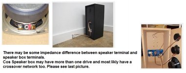
I measured the impedance at the speaker output terminals in the Amp and here it reads around 1-1.5 ohm. My rear speakers are fitted in cabinets at rear wall of my room where tweeters are fitted in the cabinet door so I can see the terminals when I open the door. There I measured impedance on one of the tweeter and it reads around 4 ohm which close to the written 4 ohm rating on them.
I didn't measure impedance of the woofer cones but it should also be same as rating is written 4 ohm on them.
Shouldn't we take the AMP speaker output terminal reading seriously as that is combined impedance?
May be the total combined impedance is turning out into 1-2 ohm since there are two drivers (woofer+tweeters rated @ 4ohms) in each speaker-set? If that is the case then how do I bring down the impedance to 4 ohm?
I am not using crossovers, using just HF capacitors on tweeters.
Hi Jack
i am going thro same issue.. i started with with wintek and burd it now using lumin every thing is okay but no sound ? any help
iam from pune
i am going thro same issue.. i started with with wintek and burd it now using lumin every thing is okay but no sound ? any help
iam from pune
Can't exactly guess what went wrong. This amp is very simple to build. Can you measure the speaker output coming from the amp? If you can post your connection diagram and photos then it may help understanding the issue.Hi Jack
i am going thro same issue.. i started with with wintek and burd it now using lumin every thing is okay but no sound ? any help
iam from pune
Last edited:
- Home
- Amplifiers
- Chip Amps
- Help Needed on DIY LM3886 based 5.1 Channel AMP for PC Home Theater