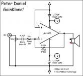
I've been an avid speaker building for while now and have decided to dive into the world audio electronics with building a gainclone. I would like to base my design on Peter Daniel's Gainklone, but have run into a few problems.
1) While looking through the manual of my DVD/CD/Everthing Player it said that the audio output was ... "2.0v (rms), 330 ohm, pin jack(L,R) * 1." does this mean that log pot on the circuit needs 330 ohms, or does it need to be 50k or 100 ? Because I thought the ouput impedence on most CD players was 100k. And if I changed the value of the pot would this affect the 4.7uF input cap ?
2) I also have a salvaged shielded E+I type transformer from a stereo sony amp, that I would like to use. Its secondary voltage is about 30V but I don't have know clue about how many amps. Is there any easy way I can measure this or guestimate it ?
(PS the transformer was used to drive the STK 4913 stereo amp and a equalizer circuit if this is any help ?)
Attachments
audioaction said:1) While looking through the manual of my DVD/CD/Everthing Player it said that the audio output was ... "2.0v (rms), 330 ohm, pin jack(L,R) * 1." does this mean that log pot on the circuit needs 330 ohms, or does it need to be 50k or 100 ? Because I thought the ouput impedence on most CD players was 100k. And if I changed the value of the pot would this affect the 4.7uF input cap ?
330 ohm output impedance is normal. Source components will typically have output impedances ranging from 100 ohms to perhaps 1,000 ohms. Using the 50k pot will be just fine. Since we're interested in maximum voltage transfer rather than maximum power transfer, you ideally want a low output impedance and a high input impedance.
2) I also have a salvaged shielded E+I type transformer from a stereo sony amp, that I would like to use. Its secondary voltage is about 30V but I don't have know clue about how many amps. Is there any easy way I can measure this or guestimate it ?
(PS the transformer was used to drive the STK 4913 stereo amp and a equalizer circuit if this is any help ?)
Don't worry about it. Just use a whole lot of reservoir capacitance. 😀
se
The reason I would like to know the amperage (or however the hell its spelled) is so that I could incorporate one the blue LEDS and maybe a cpu cooling fan from a laptop. And also can I substitue pot values without really affecting the design that much and if so by how much. The reason I ask this is that I need a smaller sized pot to fit into my compact design and the local parts store doesn't have any of the smaller sized 50k pots.
audioaction said:The reason I would like to know the amperage (or however the hell its spelled) is so that I could incorporate one the blue LEDS and maybe a cpu cooling fan from a laptop. And also can I substitue pot values without really affecting the design that much and if so by how much. The reason I ask this is that I need a smaller sized pot to fit into my compact design and the local parts store doesn't have any of the smaller sized 50k pots.
An LED and a little CPU fan aren't going to suck up much current. Though some would probably recommend powering the fan with a separate supply anyway, regardless of how large your power transformer is, just to reduce any noise on the rails.
You can easily go with a 25k or 10k pot without any problems.
se
I'm still pretty weak on how signal attenuation works but would a 100k pot do just as well or if I eliminate the volume control all together will I need to change any other of the components ?
audioaction said:I'm still pretty weak on how signal attenuation works but would a 100k pot do just as well or if I eliminate the volume control all together will I need to change any other of the components ?
A 100k pot would work ok. Though you might want to increase the value of the input capacitor a bit because it will result in a bit higher source impedance at its mid-resistance point and would roll off a little more bass than with a 50k. Though 4.7uF is a good amount of capacitance so the difference isn't going to be huge.
Attenuation works, in this case at least, by the pot acting as a simple voltage divider. It's basic Ohm's Law.
The source effectively sees the pot as a single resistor (seeing as the source is tied across the two ends of the pot) its value being the value of the pot.
So let's use the 50k pot as an example and say your CD player is outputting a 2 volt signal.
The current (I) through the resistor, as per Ohm's Law will be voltage (E) divided by resistance (R), or I = E/R. So if E is 2 volts and R is 50k, I will be 2/50,000 which is 0.00004 amps or 40 microamps.
With the pot turned all the way up (i.e. no attenuation) your Gainclone will see the full 2 volts being output by the CD player.
Ohm's Law also says that if you have a given current flowing through a given resistance, you'll have a given voltage across it by way of E = I x R.
So let's turn the pot to its half resistance point. Now your Gainclone is seeing the voltage across half the resistance of the pot, in this case 25k. Since the current through that resistance is the same as the current that's flowing through the entire resistance of the pot we can use the same value of current as before. I is 0.00004 amps and R is 25,000 ohms. 0.00004 x 25,000 = 1.
So your Gainclone's now seeing just a 1 volt input rather than 2 volts. That's half the voltage it was seeing before so the attenuation, in decibels is 20 x log 0.5 or -6.02dB.
Of course as you continue to turn down the pot the resistance across which the Gainclone's getting its input voltage gets smaller and smaller and subsequently the input voltage gets smaller and smaller.
This help?
se
nothing ventured, nothing gain-cloned...?
I am not a GC fan... as many will have realized, Particularly Steve and Peter...
As I'm sure everyone has realized, this inverting arrangement causes continuously variable Z(in) and therefore NFB with volume adjustment - yes, small but significant enough (at least to me). Especially if the source is possibly a tube pre-amp, some of which can have unusually high Z(out).
The non-inverting GC would be a better bet in my opinion, unless the pot is removed and volume adjusted in the source alone. As it stands, it is not a model of sound EE.
Enough is enough ,at this point i am putting DrG on ignore.
I would not suggest a cpu cooling fan as any running motor near the chip can make interference. I tried motorized pots on my GC and every time i changed volume i could hear a buzz.Any thing that affects the low noise floor will affect the performance.
ro
I would not suggest a cpu cooling fan as any running motor near the chip can make interference. I tried motorized pots on my GC and every time i changed volume i could hear a buzz.Any thing that affects the low noise floor will affect the performance.
ro
Another question I have is , if I did go with a 100k pot Steve Eddy mentioned I might want to increase the value of the input cap ? Are there any specific rules for doing this and why. I understand the rules of attenuation better but how would this affect the input cap if I went with a 100k pot ?
If you have a stable source ie.cd player , pre amp and <.003v from the source there is no need or an input cap. I dont use one and only did on my first GC ad i am on my 9th right at the moment. I keep selling them to friends who are very impressed with the sound.
ron
ron
So basically the input cap is more a precautionary measure, because I read on the decibel dungeon website that it is recommended to get a fairly high quality one.
The reason the input cap is there is to keep DC out of the signal path.If the source has no or very little DC <.003v then it is not necessary and the sound is clearer without it.
ron
ron
Earlier in this I wrote that the product manual specs said my players output was "2.0v (rms), 330 ohm, pin jack(L,R) * 1." Now to me that looks quite a bit more than .003v. So I guess I do need a input cap ?
audioaction said:Earlier in this I wrote that the product manual specs said my players output was "2.0v (rms), 330 ohm, pin jack(L,R) * 1." Now to me that looks quite a bit more than .003v. So I guess I do need a input cap ?
The 2 volts RMS is the full scale output of your CD player. What Ron's talking about, the 0.003 volts, is the DC offset voltage at the output of your CD player. This is the DC voltage present at the output when no signal is being output. Your CD player may well have an output coupling cap which would make this issue moot.
se
I used a fan on one of my gainclones and I powered the fan with a wallwart. It seems to work well. I installed a thermostat that I had ordered for $.50 so that when the temperature gets to 107degrees F the thermostat closes and activates the fan. When the temperature gets to 90 degrees F the therostat opens and the fan turns off. It works really well and the only time the fan operates is when I am jamming hard. I know it may introduce some noise but I just wanted to experiment with a fan and I cannot discern any noise because the music is loud when the fan kicks in. I am using my gainclone with 4 ohm homebrew speakers and 28 volt rails. I am using Allen-Bradley resistors and cheap caps and still it sounds wonderful. I just used this arrangement until I could afford to buy better parts. I have built 3 gainclones and I am completely satisfied. It is a simple circuit and regardless of whether or not people are fans of the gainclone it offers a hell of a lot better sound than most of the cheap *** receivers on the market.
Oh yeah I got the thermostats here www.bgmicro.com
I checked but they seem to be sold out. They also have alot of other parts pretty reasonably priced.
Oh yeah I got the thermostats here www.bgmicro.com
I checked but they seem to be sold out. They also have alot of other parts pretty reasonably priced.
- Status
- Not open for further replies.
- Home
- Amplifiers
- Chip Amps
- help needed in designing gainclone