Hi all,
I have been in a journey of learning with my first tube amp, since 2012. Managed to get it working 4years later, due to budget constraints. And re-case and get it singing again 4years later. This time is a family commitment stuffs which delayed my hobby. Due to the long delay, the wooden case i build, also started to crack along the joint. Yeah poor workmanship do contribute as well. 😀


The schematic is from a chinese source, it looks simple, so started to buy a kit from them, and start assembling. Well I did not liked the PCB due to some burnt tracks and stuffs, so i re-case it. unfortunately meeting various problems and doubt since version 1. Hope someone can help me understand and give some direction to me.

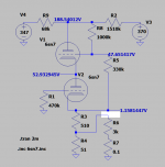
Initially had problem with the 215V and 345V. That was solved by changing the resistors to 5.1K(for 215V) and 5.4K(for 345V). Now i am getting 217V and 347.5V.
My problem is now, getting 48V on 6SN7. I could only get 30V in the original schematic state.
Had a friend told me to tweak the 330K to something bigger. I tried, but it wont bring the voltage up a lot, and I dont think thats the correct way. Somehow it sounded weird. I changed it to 520K and its up from 30V to 36V. I think i will change it back to 330K.
1. Should I tweak 68K instead?
Pencil values are in quite different state. Please ignore them.
2. I am using star ground. its on the middle, lower left of the picture. But I am hearing some medium/high frequency noisy. 20-30mV per channel. Any tips on how to rectify this?
3. For the 680µF on the bias, is it necessary to be such high value?
Thank you for reading, hope i can get some kind help and guidance.
I have been in a journey of learning with my first tube amp, since 2012. Managed to get it working 4years later, due to budget constraints. And re-case and get it singing again 4years later. This time is a family commitment stuffs which delayed my hobby. Due to the long delay, the wooden case i build, also started to crack along the joint. Yeah poor workmanship do contribute as well. 😀
The schematic is from a chinese source, it looks simple, so started to buy a kit from them, and start assembling. Well I did not liked the PCB due to some burnt tracks and stuffs, so i re-case it. unfortunately meeting various problems and doubt since version 1. Hope someone can help me understand and give some direction to me.
Initially had problem with the 215V and 345V. That was solved by changing the resistors to 5.1K(for 215V) and 5.4K(for 345V). Now i am getting 217V and 347.5V.
My problem is now, getting 48V on 6SN7. I could only get 30V in the original schematic state.
Had a friend told me to tweak the 330K to something bigger. I tried, but it wont bring the voltage up a lot, and I dont think thats the correct way. Somehow it sounded weird. I changed it to 520K and its up from 30V to 36V. I think i will change it back to 330K.
1. Should I tweak 68K instead?
Pencil values are in quite different state. Please ignore them.
2. I am using star ground. its on the middle, lower left of the picture. But I am hearing some medium/high frequency noisy. 20-30mV per channel. Any tips on how to rectify this?
3. For the 680µF on the bias, is it necessary to be such high value?
Thank you for reading, hope i can get some kind help and guidance.
Attachments


> I am hearing some medium/high frequency noisy
The box is beautiful to the eye. But it is totally transparent to ALL the electric crap in the room. I would expect much powerline buzz. In modern homes you also have your cellphones, wifi, and other electronic gizmos. There's a reason "ALL" audio is done in metal boxes, or with conductive lining of plastic/wood cases.
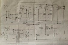
I have no idea if the original plan "should" work. It seems a mess, and badly copied. Here's a straighter contrastier copy but I'm too sleepy to look at it.
The box is beautiful to the eye. But it is totally transparent to ALL the electric crap in the room. I would expect much powerline buzz. In modern homes you also have your cellphones, wifi, and other electronic gizmos. There's a reason "ALL" audio is done in metal boxes, or with conductive lining of plastic/wood cases.
I have no idea if the original plan "should" work. It seems a mess, and badly copied. Here's a straighter contrastier copy but I'm too sleepy to look at it.
Attachments

It looks like you use the 9k1 and 12k resistors you change to 5k1 and 5k4 for the two channels in common. Wasn't planed that way, was each channel it's own resistors, and zeners! Now with the extra current perhaps the zeners will overheat.
By changing the 12k the following 10µF gets a little small, if you half the resistor you should double the capacitor to get the same amount of hum reduction.
Mona
By changing the 12k the following 10µF gets a little small, if you half the resistor you should double the capacitor to get the same amount of hum reduction.
Mona
Check 220u/16v e-cap across 510 ohms resistor in cathode of 6sn7. If it's shorted or polarity reversed, the bias for both sections will be reduced. The cathode voltage should be about 1.2V, and the top 6sn7 bias around -5V and plate voltage should be around 190V.My problem is now, getting 48V on 6SN7. I could only get 30V in the original schematic state.
Attachments
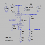
Yes, could be cathode decoupling, but on the photos they seem to be in the right direction.Check 220u/16v e-cap across 510 ohms resistor in cathode of 6sn7. If it's shorted or polarity reversed, the bias for both sections will be reduced. The cathode voltage should be about 1.2V, and the top 6sn7 bias around -5V and plate voltage should be around 190V.
This amp is a modified one with Chinese FU-7 (~807) tubes.
Adapted the cathode resistor and decoupled the power resistors.
And also made the feedback even less, from 2k to 3k.
And Koonw, that 3k goes to the 51Ω not to the cathode 😉
Mona
Attachments
> I am hearing some medium/high frequency noisy
The box is beautiful to the eye. But it is totally transparent to ALL the electric crap in the room. I would expect much powerline buzz. In modern homes you also have your cellphones, wifi, and other electronic gizmos. There's a reason "ALL" audio is done in metal boxes, or with conductive lining of plastic/wood cases.
I have no idea if the original plan "should" work. It seems a mess, and badly copied. Here's a straighter contrastier copy but I'm too sleepy to look at it.
thank you for your advice. seems like i will be having more case work need to be done. maybe i will shorten the leads and add an aluminium shield below the component.
It looks like you use the 9k1 and 12k resistors you change to 5k1 and 5k4 for the two channels in common. Wasn't planed that way, was each channel it's own resistors, and zeners! Now with the extra current perhaps the zeners will overheat.
By changing the 12k the following 10µF gets a little small, if you half the resistor you should double the capacitor to get the same amount of hum reduction.
Mona
your prediction was straight on. previously i saw the small wattage zeners nearly melted. i had to use higher wattage zeners. now i know why...😀
for the 12K, i think if i separate them into 2 channels, with 2 caps(as intended inside the schematic that i missed), voltage might be correct without adjustment. thank you for the experienced analysis and sharing Mona.

Check 220u/16v e-cap across 510 ohms resistor in cathode of 6sn7. If it's shorted or polarity reversed, the bias for both sections will be reduced. The cathode voltage should be about 1.2V, and the top 6sn7 bias around -5V and plate voltage should be around 190V.
have be able to setup my worktable and check on the circuit yet. THank you koonw for the voltage simulation and experienced advice
. will check the cap connection. Yes, could be cathode decoupling, but on the photos they seem to be in the right direction.
This amp is a modified one with Chinese FU-7 (~807) tubes.
Adapted the cathode resistor and decoupled the power resistors.
And also made the feedback even less, from 2k to 3k.
And Koonw, that 3k goes to the 51Ω not to the cathode 😉
Mona
sharp eyes Mona.