Hi all,
here is a hard one for all you aficionados of electronics.
I am looking for a way to get a STABLE and Exact 100 Volts drop for a very low current application.
What i'm trying to achieve, is use a cheap 100 volt digital panel meter for measuring (monitoring) a voltage of around 140 to 170 volts area. So i will be adding 100 volts in my final measurement. For example, 152.7 volts will be displayed as 52.7.
Now i know that higher voltage meters exist, but i cannot order one right now, so i would like to proceed with what i have at hand.
I tried using a 100 volt 1.3 watt zener diode in it's reverse breakdown region, but with limited success, as far as accuracy goes, getting an error of -2 to -7 (!) volts, depending on the voltage being measured or the temperature of the zener.
The meter has an internal resistance of 75.9 ΚΩ, which i find freakingly low for a highish voltage meter, but on the other hand is enough to drive the zener current.
In case you're wondering, i'm building (i've build) a CC trickle charger/discharger for the traction battery of a hybrid car (NiMH), with a nominal voltage of 144 volts (120 cells in series), for balancing out the cells every now and then. The car only uses the battery from 40% to 80% of it's capacity, and only has balancing for every 12 cells in series (10 points),
so with time some weak cells do appear and capacity is dramaticaly decreased. The only way to bring it back is with a periodic full charge at a safe current.
Actually, 3 charge/discharge cycles gives excellent results!
So, comming back to the matter at hand, is there any other way to get a more stable and acurate 100 volt drop? Any ideas??
Thanks for any input!
How about looking at it a bit sideways. I think dropping exactly 100V would be difficult. Might it be OK if you simply used a voltage divider and measured 1/2 of the voltage there (really easy to do with 2 matched resistors). Its not much harder to multiply the result by 2 than it is to stick a 1 in front of the reading...So, comming back to the matter at hand, is there any other way to get a more stable and acurate 100 volt drop? Any ideas??
Thanks for any input!
Rich
Use a triac or capacitor based fan dimmer, and a digital meter, should work.
Use a half wave rectifier, it seems pulse charging is more effective.
If already full bridge, remove the caps.
That is for lead acid, should work on your batteries too.
Use a half wave rectifier, it seems pulse charging is more effective.
If already full bridge, remove the caps.
That is for lead acid, should work on your batteries too.
Meter is to check, the mains powered meters are about $3 here, they indicate the mains voltage, which is their power too, so they have two wires only...
They work in the range 90-260V, should be fine before rectifier.
They work in the range 90-260V, should be fine before rectifier.
"so i would like to proceed with what i have at hand" -> the mother of design errors

🙂
Really, sometimes we get odd restrictions.
Like I have only this, and make it work!
Get hold of a Variac, play with it till satisfied.
Really, sometimes we get odd restrictions.
Like I have only this, and make it work!
Get hold of a Variac, play with it till satisfied.
Thanks for the answers everyone!
I was thinking of trying a current source, something like this to stabilize the zener current and hopefuly get a better reading,
but i actually like the idea of dividing by 10 more.
This was my first thought, which i tried, but did not like the result at all. Totaly not practical to multiply by two every time you look at the meter.How about looking at it a bit sideways. I think dropping exactly 100V would be difficult. Might it be OK if you simply used a voltage divider and measured 1/2 of the voltage there (really easy to do with 2 matched resistors). Its not much harder to multiply the result by 2 than it is to stick a 1 in front of the reading...
Rich
That i like, might try that one! Maybe a 680k resistor with a 100k trimpot in series to fine tune the acuracy.Or scale it by a factor of 10 using a voltage divider and move the decimal point.
Tom
HA! Absolutely true, but it won't stop me!"so i would like to proceed with what i have at hand" -> the mother of design errors
I was thinking of trying a current source, something like this to stabilize the zener current and hopefuly get a better reading,
but i actually like the idea of dividing by 10 more.
ANY cheap multimeter has a scale-of-2 selector (0.2 - 2 - 20 - 200 whatever) so just use the 200VDC scale, period.
It will measure the 140 to 70V DC area BEAUTIFULLY.
Why waste time on unreliable kludges is way beyond me.
As of:
I am baffled about this nonsense/gibberish and find NO WAY it answers or helps the OP´s question.
It will measure the 140 to 70V DC area BEAUTIFULLY.
Why waste time on unreliable kludges is way beyond me.
As of:
Use a triac or capacitor based fan dimmer, and a digital meter, should work.
Use a half wave rectifier, it seems pulse charging is more effective.
If already full bridge, remove the caps.
I am baffled about this nonsense/gibberish and find NO WAY it answers or helps the OP´s question.
He wants 220 in 155 out, so as to charge a car battery.
That is not even relevant in an audio forum.
Simple ways given above, for somebody who might get himself killed.
As it is he has no experience it seems:
"Now i know that higher voltage meters exist, but i cannot order one right now, so i would like to proceed with what i have at hand."
OP: those voltages can be fatal. Beware.
Actually I'd take ten 100 kΩ and put them in series. This could be built on a piece of prototype board in ~15 minutes. Connect the two ends to the voltage you'd like to measure and the meter across one of the resistors. This forms a 900 kΩ : 100 kΩ voltage divider.That i like, might try that one! Maybe a 680k resistor with a 100k trimpot in series to fine tune the acuracy.
Vout = Vin*(100/(100+900)) = Vin/10
Use ±1% tolerance resistors. This way you won't have to mess with potentiometers and such. You could even use a resistor network/array (i.e., many resistors in one package) and take advantage of the matching between resistor elements.
This method does require that the input impedance of the meter is high. 10 MΩ input impedance would result in a 1% error unless you compensate for the input impedance by making the sense resistor a bit higher in value. If you do need better precision than ±1%, you can consider adding a pot for adjustment. I'd check the precision of the meter first, though. Cheap panel meters are usually not very precise.
Tom
OP is using a panel meter. They often don't have a range selector.ANY cheap multimeter has a scale-of-2 selector (0.2 - 2 - 20 - 200 whatever) so just use the 200VDC scale, period.
Why waste time on unreliable kludges is way beyond me.
It could be worth looking into whether the meter does have a way to increase the range, though. Maybe one could move a 0 Ω resistor jumper or something.
Tom
He wants a shunt design so as to use an existing 0-100 volt meter to display actual (-) 100 volts.
For $3, you are wasting a lot of people's time.
For $3, you are wasting a lot of people's time.
Just get a new one...
Samples:
https://beimeter.com/digital-panel-meters/
https://www.hnhcart.com/products/4-...MI7OuevI_G9gIVf8EWBR242wMPEAQYAiABEgJg_fD_BwE
Many more suppliers in China, for example.
Or get one from scrap / closure sales.
Samples:
https://beimeter.com/digital-panel-meters/
https://www.hnhcart.com/products/4-...MI7OuevI_G9gIVf8EWBR242wMPEAQYAiABEgJg_fD_BwE
Many more suppliers in China, for example.
Or get one from scrap / closure sales.
Last edited:
I have already installed on the charger box the panel meter, which also displays the current. So a multimeter is no good, even though i have plenty.ANY cheap multimeter has a scale-of-2 selector (0.2 - 2 - 20 - 200 whatever) so just use the 200VDC scale, period.
It will measure the 140 to 70V DC area BEAUTIFULLY.
Why waste time on unreliable kludges is way beyond me.
I think he was refering to the charging topology, and the fact that pulsed charging brings good results. This is actually true for NiMH, but i have already built/tested my charging circuit with excellent results!I am baffled about this nonsense/gibberish and find NO WAY it answers or helps the OP´s question.
I have posted in the General Interest section of a forum which contains the words EVERYTHING and ELSE right on the title....He wants 220 in 155 out, so as to charge a car battery.
That is not even relevant in an audio forum.
Simple ways given above, for somebody who might get himself killed.
As it is he has no experience it seems:
"Now i know that higher voltage meters exist, but i cannot order one right now, so i would like to proceed with what i have at hand."
OP: those voltages can be fatal. Beware.
Also don't worry, i have plenty of experience with power electronics and high energy systems, and never have come even close to being in danger! If anything, i am carefull to a degree of paranoia.
That would be my first direction, but as i said earlier, the voltage meter part of the panel meter only has a 75.9 kΩ resistance. So a series divider is in order.Actually I'd take ten 100 kΩ and put them in series. This could be built on a piece of prototype board in ~15 minutes. Connect the two ends to the voltage you'd like to measure and the meter across one of the resistors. This forms a 900 kΩ : 100 kΩ voltage divider.
Vout = Vin*(100/(100+900)) = Vin/10
Use ±1% tolerance resistors. This way you won't have to mess with potentiometers and such. You could even use a resistor network/array (i.e., many resistors in one package) and take advantage of the matching between resistor elements.
This method does require that the input impedance of the meter is high. 10 MΩ input impedance would result in a 1% error unless you compensate for the input impedance by making the sense resistor a bit higher in value. If you do need better precision than ±1%, you can consider adding a pot for adjustment. I'd check the precision of the meter first, though. Cheap panel meters are usually not very precise.
Tom
Fair, but i want to do it this way because i have already installed the meter and a new one will take one or two months to come from the east, and also as an excercise for the mind. I know it can be done. I was just asking for your/new ideas to make it elegant, yet functional.He wants a shunt design so as to use an existing 0-100 volt meter to display actual (-) 100 volts.
For $3, you are wasting a lot of people's time.
My point is "One can buy a proper panel meter, but one can't buy the joy of hacking the improper one, and doing their job like a boss" 😎
The problem is relatively easily solvable with a few more components. I don't know whether it's worth the trouble, but here it is anyway:

The configuration is a bridge, to eliminate marginal parasitic effects.
The total voltage of the zeners should be 100V. D1 to D3 can be a single diode of the right voltage, but adjustment is easier if one has a lower breakdown: you could use 82V and 13V for example, or any other combination.
The sim shows the voltage across the voltmeter when the input is swept from 100V to 200V
The GND is placed arbitrarily at a convenient place for the sim, but it shouldn't be replicated in reality
I don't know much about these specifics, but I try to live by
Do it the right way, the first time.
There are a bunch of panel meters on Amazon, that go beyond 100V, that have one day shipping. One day is a small price to pay for future hassles. Will you (or someone else) remember to add 100 or divide by 2 or whatever?
Do it the right way, the first time.
There are a bunch of panel meters on Amazon, that go beyond 100V, that have one day shipping. One day is a small price to pay for future hassles. Will you (or someone else) remember to add 100 or divide by 2 or whatever?
Jinny Cricket on a pogo stick. Nobody here knows basic electricity?
This needs a voltage reference and (because no voltage is zero-impedance) a stable current.

The job is "traction battery of a hybrid car", which sure suggests that ample current is available. Even if this is a model car.
A Zener is OK if the current hardly varies. The meter models as a 76K resistor so current will vary. We need a stable larger current. Because a Zener is not SO soft, I picked 4mA. A simple transistor current source is more than solid enough. The base reference may be a low-Voltage Zener. I set the base Zener current at 15mA but it would be fine (and much cooler) with R449 at 100k, 1.5mA.
The meter is grounded which may matter (for its power or for user safety/comfort).
A 2N2222 is not rated for the >100V possible but 140V 600mW parts may be available? (If your local supply chain for even minor parts is truly locked-down, then the whole problem becomes intractable.)
would like to proceed with what i have at hand.
This needs a voltage reference and (because no voltage is zero-impedance) a stable current.
The job is "traction battery of a hybrid car", which sure suggests that ample current is available. Even if this is a model car.
A Zener is OK if the current hardly varies. The meter models as a 76K resistor so current will vary. We need a stable larger current. Because a Zener is not SO soft, I picked 4mA. A simple transistor current source is more than solid enough. The base reference may be a low-Voltage Zener. I set the base Zener current at 15mA but it would be fine (and much cooler) with R449 at 100k, 1.5mA.
The meter is grounded which may matter (for its power or for user safety/comfort).
A 2N2222 is not rated for the >100V possible but 140V 600mW parts may be available? (If your local supply chain for even minor parts is truly locked-down, then the whole problem becomes intractable.)
Thank you very much PRR,
that is exactly the sort of idea that i was after!
I have a stash of MJE 340/350s from older audio projects, which iirc are high voltage and should do just fine.
Will report back next weekend.
that is exactly the sort of idea that i was after!
I have a stash of MJE 340/350s from older audio projects, which iirc are high voltage and should do just fine.
Will report back next weekend.
Thanks everyone, and especially tomchr,
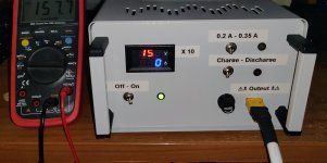
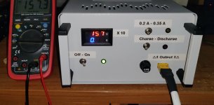
finaly i went with the divide by 10 scheme of things, as i felt it was the simplest and most elegant solution. Don't even need the resolution... just the accuracy!
All it took was a resistor and a 10 turn trimpot. It works beautifuly AND is rock stable and accurate.
Just realized that the camera exposure time messes up with the panel meters refresh rate! But you should get the idea.
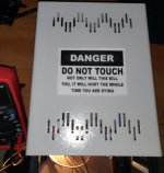
Last photo, that label will be glued on top of the unit (which anyway will be operated exclusively by me), just in case.
finaly i went with the divide by 10 scheme of things, as i felt it was the simplest and most elegant solution. Don't even need the resolution... just the accuracy!
All it took was a resistor and a 10 turn trimpot. It works beautifuly AND is rock stable and accurate.
Just realized that the camera exposure time messes up with the panel meters refresh rate! But you should get the idea.
Last photo, that label will be glued on top of the unit (which anyway will be operated exclusively by me), just in case.
Attachments
- Home
- General Interest
- Everything Else
- Help needed for dropping 100 volts!