Hey all,
I'm trying to repair a friends Amp that refuses to power up.
I've narrowed it down to the power supply section of the Microcontroller.
I've replaced transistors Q1-Q3 (MPSA55) and Q2-Q4 (MPSA05) and the U32 (L4940V5) which is a Fixed 5volt LDO Regulator with a Zener (D14) added at the Ground PIN to output 5.6volt.
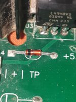
Need some help to identify the two Zener Diodes D4 and D14.
K1 (High Voltage Relay) is 12volt.
Thanks in advance.
Attachments
D4 and D14 are regular small signal diodes 1n4148
d4 is flyback diode to protect rest of the circuit from voltage from inductor (coil from the relais)
d14 lifts the "ground" terminal of the 5V regulator by aprox. 0,6v, hence output with reference to ground is 5,6V
Hope this helps
d14 lifts the "ground" terminal of the 5V regulator by aprox. 0,6v, hence output with reference to ground is 5,6V
Hope this helps
Thanks mate, much appreciated.D4 and D14 are regular small signal diodes 1n4148
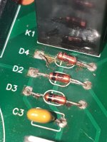
Any idea about what D2 and D3 might be?d4 is flyback diode to protect rest of the circuit from voltage from inductor (coil from the relais)
d14 lifts the "ground" terminal of the 5V regulator by aprox. 0,6v, hence output with reference to ground is 5,6V
Hope this helps
OK, figured out D2 and D3 are also 1N4148
Problem now is that I measure 10.8volts at D4 where I should measure 12volt, K1 Relay goes into "oscillation" and doesn't "lock", any suggestions?
Problem now is that I measure 10.8volts at D4 where I should measure 12volt, K1 Relay goes into "oscillation" and doesn't "lock", any suggestions?
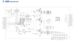
D2 and D3 (ref sch 1of 3 or untiteld2. jpg) appear to serve as line monitor (line as in power/voltage from transformer), hence line mon
The amplifier probably has some sort of always on / standby mode. btw you might want to check the fuses / fusable resistors R1 and R2.
If these are open (not low ohmage) then bigger problems lay ahead.
The line mon signaltrace goes to ref sch 2 of 3 or untiteld.jpg and there gets amplfied Q1,Q2) and normalized with pull up resistors R9 to signal the microcontroller ma 6300 to start or stop. Make sure the 5.6V supply VDD is their to begin with. Otherwise the circuit will not get power and won't function.
Without further schematic and precise description of failure mode diagnosis is difficult.
I measure 5.45volts at the output of the L4940V5 not a solid 5.6volts.
Attached is the full Service Manual if you have the time to take a look.
Thanks.
Attached is the full Service Manual if you have the time to take a look.
Thanks.
Attachments
Last edited:
5.45 volts is OK. No biggie
The output relay oscillating is a biggie
It means the power amplifier is triggering the protection circuit
Schematic needed is HEATSINK 050280 SCH 1 OF 3
Short story:
One more more output / driver transistors are blown. DC on output triggers K1 oscillation.
So not the control circuitry.
Diagnosing this will be a bit more involved.
With the amplifier off, power disconnected and starting with the output transistors you will have to check each transistor in circuit.
If you get funny readings take the transistor from the board and measure. Make sure to check surrounding resistors as well.
Work your way back to the input.
You could even try to disconnect both power amplifier from the supply. then check with the amp powered if the control circuitry functions correctly.
If you are not confident (i.e. have enough knowledge) to do this don't
- Home
- Amplifiers
- Solid State
- Help needed for an Amplifier repair


