I picked up a nice looking PCB on ebay from a gent named HVForLess. It's an Aikido input (credit to John Broskie) with a White Cathode Follower output. It also has a house ground isolation circuit. Uses (2) 6SN7 input tubes and (2) output tubes being either 6BX7 or 6BL7 depending on R11 and R17 values used.
I first started up the amp with just the rectifier and dialed in the 6.3v heater voltage using the first trimmer resistor. I then put the 6SN7s and 6BL7s in and turned it on. R24 smoked a little... it was dissipating a lot of heat as I initially measured 160V for the high voltage, however once I adjusted the second trimmer and got it to the 300V needed, the resistor cooled down. I chatted with HVforLess about this, he said R24 should be 22K rather than the 6.2K in his original BOM, so I swapped it out.
The build holds smoke perfectly well, but the DC offset is super high. 640 mV for both the right and left channels. I've looked at this puppy 6 ways to Sunday, confirmed every resistor is the right value, every cap is the right value, all the diodes and caps are in the right orientation. I'm already pretty obsessive with builds (every resistor gets measured and matched on the right and left), all the parts come from Mouser, etc. The resistors are carbon film or carbon comp, so usually about 1-3% less than their stated value, but that shouldn't be enough to throw anything off here.
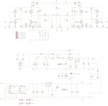
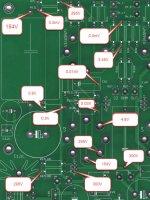
I measured the voltage in several areas (see attached files with the little red word bubbles)... these are all referencing the headphone output ground. I'm hoping someone may notice something awry here. I can certainly take more measurements as needed. The schematic is also attached below, as well as the original inspiration Aikido schematic which hvforless provided me.
Here's a photo of the PCB

Here's my build


Ignore the incorrectly used IEC filter in the second photo, It was removed and the only wired ground connection goes from the IEC inlet ground to the PCB ground as shown in the schematic for the house ground isolation. The PCB has a ground that ties to a standoff to the chassis.
...no traces were harmed in the modification of the PCB if anyone is wondering.
If anyone has an suggestions to try I would REALLY APPRECIATE IT! TIA.
I first started up the amp with just the rectifier and dialed in the 6.3v heater voltage using the first trimmer resistor. I then put the 6SN7s and 6BL7s in and turned it on. R24 smoked a little... it was dissipating a lot of heat as I initially measured 160V for the high voltage, however once I adjusted the second trimmer and got it to the 300V needed, the resistor cooled down. I chatted with HVforLess about this, he said R24 should be 22K rather than the 6.2K in his original BOM, so I swapped it out.
The build holds smoke perfectly well, but the DC offset is super high. 640 mV for both the right and left channels. I've looked at this puppy 6 ways to Sunday, confirmed every resistor is the right value, every cap is the right value, all the diodes and caps are in the right orientation. I'm already pretty obsessive with builds (every resistor gets measured and matched on the right and left), all the parts come from Mouser, etc. The resistors are carbon film or carbon comp, so usually about 1-3% less than their stated value, but that shouldn't be enough to throw anything off here.
I measured the voltage in several areas (see attached files with the little red word bubbles)... these are all referencing the headphone output ground. I'm hoping someone may notice something awry here. I can certainly take more measurements as needed. The schematic is also attached below, as well as the original inspiration Aikido schematic which hvforless provided me.
Here's a photo of the PCB
Here's my build
Ignore the incorrectly used IEC filter in the second photo, It was removed and the only wired ground connection goes from the IEC inlet ground to the PCB ground as shown in the schematic for the house ground isolation. The PCB has a ground that ties to a standoff to the chassis.
...no traces were harmed in the modification of the PCB if anyone is wondering.
If anyone has an suggestions to try I would REALLY APPRECIATE IT! TIA.
Attachments
Last edited:
Listing with all details below from: DIY PCB Board OTL Tube Headphone Amp Aikido White Cathode Follower 6SN7 6BX7 | eBay
Code:
[I]I started this auction by selling extra boards from a personal project.  The reception was great so I had more made and made a few improvements.  The original goal of this project was to have a compact octal tube OTL headphone amplifier that would drive low impedance headphones (down to 32 Ohm).  I chose an Aikido input with a White Cathode Follower output (input/output stage design credit to John Broskie of TubeCad).  Sounds easy enough to pull off but the power supply requirements were a bit tricky.  I wanted to use a single standard power transformer with high voltage and filament supply.  I also wanted an external choke.  All those needs forced a custom PCB.  The tricky thing was the power supply design with DC heaters in mind.  To drive low impedance headphones with the Aikido circuit requires the use of 6BX7 or 6BL7 output tubes.  Those pull 1.5A each.  With 6SN7 input tubes the entire heater draw adds up to 4.2A of DC current.  That's not trivial.  After a few tries I made some great boards that work perfectly.  It sounds clean, loud, and amazing.  This will drive any pair of headphones you may own.

Heater Circuit:

Regulated 6.3VDC from 6.3VAC winding with the use of schottky diodes and super low dropout regulator.  Trimpot adjustment to dial in the final voltage.
Huge capacitance for ultra-low ripple.  45,000uF capacitance.
Full 4.2 amps of DC heater current.  High current components and heat management designed in.  Heat sink on LDO and heat sinks on all rectifying diodes.  Remember you need 1.8X the DC current from your transformer.  A safer rule of thumb is 2.0X the DC current. The transformer I use puts out 8A @ 6.3VAC.
High Voltage Circuit:

Regulated output using Maida circuit.
Huge capacitance for ultra-low ripple.  256uF capacitance.
Tube rectified power.  I like the look of the extra tube and I like the slow start.  Use a 5AR4/GZ34.  Want to use a cool looking 5U4G instead, just ask how.
Designed for external choke filter (C-L-C).
Ridiculously quiet power.
Additional Features:

¼ B+ reference circuit built in.  Elevates the heater ground to ¼ of the B+ voltage.  Provides for hum free power and max heater/cathode difference isn't exceeded.
House ground isolation circuit built in.  House ground attach to the board for a hum free experience.
Chassis ground tied through one of the mounting holes
Designed for use with high end audio grade components (Wima MPK series, Nichicon KX and KW series, etc).
500uF coupling capacitance on output.  I'm using a 470uF electrolytic with a 30uF film capacitor in parallel.  Response well below 20Hz.
Small and compact.  All this circuitry is smartly arranged on a 6.50” x 7.75” board.
Super thick PCB (2mm) with 2 ounce traces!!!
Schematic shown above.
The CAD I used for my case is also shown above.  I purchased a B18-HB case from Ebay.  Google "B18-HB Case" if you can't find one on Ebay.  This is the case I sized the PCB for.  Another one that's a perfect fit is "1907E".  Note that my case design is well ventilated.  Don't skimp on the airflow.  Use a bigger case otherwise.
Uses (2) 6SN7 input tubes and (2) output tubes being either 6BX7 or 6BL7.
4 jumpers are provided to switch between the (2) 6BX7 and 6BL7 output tubes.  The White Cathode Follower is a little different than most output stages.  It's optimized for a given output impedance with a given tube.  The two output tubes that work in this application are similar, but have different operating points as a result.  Instead of a compromise I fixed two output points into the design.   Move the 4 jumpers and swap tubes.  Simple.
Everything you need to build this is spoon fed.  Use this board, the BOM below, and find an appropriate case that has a volume pot and the jacks.
As described above I've designed this with jumpers so you can switch between precise operating points for 6BL7 tubes and 6BX7 tubes for headphone in the 32 Ohm range.  It's a simple task to use those jumpers to switch between 32 Ohm and 300 Ohm for one of those output tubes instead.  One user loves the 6BL7 tubes and uses this amp with 32 Ohm and 300 Ohm headphones.  The BOM below defaults to a 32 Ohm setup with tube swapping.  Make substitutions from this chart if you want the impedance option from the jumpers.

 	6BL7	6BL7	6BX7	6BX7
 	32Ohm	300Ohm	32Ohm	300Ohm
R11	270	270	290	470
R17	140	170	127	205


A BOM from Mouser is below.  I used all high end components (Wima and Nichicon Audio caps, etc).  Full schematic and board layout are above.  Please know your skill level and knowledge of electronics before considering this PCB.  If Mouser is out of something try DigiKey.  You should be comfortable specifying substitutions.

Mouser direct link for Headphone Amp BOM

Part	Value	Mouser		Alternate
C20	56uF	647-LKX2W560MESY25
C21	100uF	647-LKX2W101MESY40
C24	100uF	647-LKX2W101MESY40
C34	15kuF	647-UKW1A153MHD
C31	15kuF	647-UKW1C153MRD
C32	15kuF	647-UKW1C153MRD
C3.1L	1kuF	647-UFG1C102MHM
C3.1R	1kuF	647-UFG1C102MHM
C1.1L	470uF	871-B43508A9477M000
C1.1R	470uF	871-B43508A9477M000
C1L	30uF 400V			Parts Express
C1R	30uF 400V			Parts Express
C27	.01uF	505-MKP20.01/100/5
C28	.01uF	505-MKP20.01/100/5
C29	.01uF	505-MKP20.01/100/5
C30	.01uF	505-MKP20.01/100/5
C33	.1uF	505-MKP20.1/100/5
C35	.1uF	505-MKP20.1/100/5
C26	.1uF	505-MKP4.1/250/10P
C60	.1uF	505-MKP4.1/250/10P
C22	.1uF	505-MKP4-0.1/630/5
C23	.1uF	505-MKP4-0.1/630/5
C25	.1uF	505-MKP4-0.1/630/5
C3.2L	.22uF	505-MKP20.22/100/5
C3.2R	.22uF	505-MKP20.22/100/5
C6L	.22uF	505-MKP4J032204JKSSD
C6R	.22uF	505-MKP4J032204JKSSD
C5	4.7uF 400V	505-MKP44.7/400/10		Parts Express
D1	1N4007	621-1N4007
D3	1N4007	621-1N4007
D4	1N4007	621-1N4007
D2	1N5341	833-1N5341B-TP
D5	625-SBLF10L25-E3	625-SBLF10L25-E3
D6	625-SBLF10L25-E3	625-SBLF10L25-E3
D7	625-SBLF10L25-E3	625-SBLF10L25-E3
D8	625-SBLF10L25-E3	625-SBLF10L25-E3
KK1	SK104-PAD	532-513102B25	532-4880M
KK2	SK104-PAD	532-513102B25	532-4880M
KK3	SK104-PAD	532-513102B25	532-4880M
KK4	SK104-PAD	532-513102B25	532-4880M
KK5	SK104-PAD	532-513102B25	532-4880M
KK6	SK129-PAD	532-529802B25G	532-4880M
JP11L	3X1X2.54	571-3-644456-3	538-15-29-1024
JP11R	3X1X2.54	571-3-644456-3	538-15-29-1024
JP17L	3X1X2.54	571-3-644456-3	538-15-29-1024
JP17R	3X1X2.54	571-3-644456-3	538-15-29-1024
TR1	0-1000	594-64W102
TR2	0-1000	594-64W102
B1	RECTIFIER-GBU4	512-GBU8M
R29	100K	281-100K-RC
R10L	300	71-RN60D3000F
R10R	300	71-RN60D3000F
R11L(A)	270	71-RN60D2700F
R11L(B)	287-291	71-RN60D-F-287
R11R(A)	270	71-RN60D2700F
R11R(B)	287-291	71-RN60D-F-287
R12L	1M	71-RN60D-F-1M
R12R	1M	71-RN60D-F-1M
R13L	10k	71-RN60D-F-10K
R13R	10k	71-RN60D-F-10K
R16L	470K	71-RN60D-F-470K
R16R	470K	71-RN60D-F-470K
R17L(A)	140	71-RN60D-F-140
R17L(B)	127	71-RN60D1270F
R17R(A)	140	71-RN60D-F-140
R17R(B)	127	71-RN60D1270F
R1L	1M	71-RN60D-F-1M
R1R	1M	71-RN60D-F-1M
R20	100	660-MOS3CT631R101J
R21	100	660-MOS3CT631R101J
R22	200k-220k	281-220K-RC
R23	200k-220k	281-220K-RC
R24	6.2K	660-MOS3CT631R622J
R25	10	283-10-RC
R26	10	283-10-RC
R27	68k	660-MOS3CT631R683J
R28	300K	281-300K-RC
R2L	470	71-RN60D4700F
R2R	470	71-RN60D4700F
R30	100	281-100-RC
R3L	300	71-RN60D3000F
R3R	300	71-RN60D3000F
R4L	470	71-RN60D4700F
R4R	470	71-RN60D4700F
R5L	1M	71-RN60D-F-1M
R5R	1M	71-RN60D-F-1M
R60	10	283-10-RC
R6L	1M	71-RN60D-F-1M
R6R	1M	71-RN60D-F-1M
R7L	1M	71-RN60D-F-1M
R7R	1M	71-RN60D-F-1M
R9L	300	71-RN60D3000F
R9R	300	71-RN60D3000F
IC1	LM317	511-LM317T
IC2	BUT11ATU	512-BUT11ATU
IC3	MC29502	998-MIC29502WT
TRAN	272JX	546-272JX
CHOKE	193B	546-193B
V1(6SN7)	OCTAL			Parts Express
V2	OCTAL			Parts Express
V3(6SN7)	OCTAL			Parts Express
V4	OCTAL			Parts Express
V5(5AR4) OCTAL [/I]On the headphone output (left channel and right channel)
There are capacitors in series with the outputs so you should get nothing.
There might be a little voltage on power up but that should discharge fairly quickly.
The only problem I can think is if resistor to ground is high value and there is a bit of leakage through the electrolytic cap.
Try putting a resistor same impedance as headphones across output to ground. If DC goes away then I would remove resistor and connect head phones and try it.
I've left it running for several minutes and the DC never dropped off like with most headphone amps.
I'll give the resistor test a shot.
I'll give the resistor test a shot.
The big output caps and high-value bleeders.
Figure 1uA per uFd. 470uFd. So 470uA, or 0.47mA, times 10K, is 4.7V possible leakage no-load. In 300 Ohms, 141mV.
The actual data-sheet has a formula for leakage current, which I work out as 17.7uA. This comes to 0.177V in 10K.
You are between the rough-number and the spec-number. Put 100 Ohms on the output and let it cook for a day to form the cap. See where it comes to.
You guys called it. I put a set of resistors on the output - 38R in this case, and I'm down to a nice low 2-3mV. Normally when I measure HP amps for offset I don't add a load, but I guess this design is unique. Giving it some time to run-in now.
- Status
- Not open for further replies.
- Home
- Amplifiers
- Tubes / Valves
- Help Needed: DC Offset Too High on Octal OTL Headphone Amp (Aikido Design)