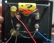
Inherited a pair of Heybrook Point Seven speakers with busted crossovers. I'm thinking of rebuilding them. Need help identifying the components though. Can anyone help? I've attached pictures for reference.
I need helps Specifically with those encircled in yellow. Any help would be most appreciated.
Thanks!
I need helps Specifically with those encircled in yellow. Any help would be most appreciated.
Thanks!
Attachments
I don't think those resistors are original. You would expect at least 3 watt resistors.
Last edited:
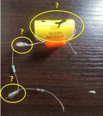
Probably( one, at least ) those are 0 resistance wires !?
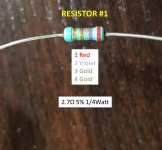
edit: oh, no, the 2.7 Ω is clearly visible ( red, purple) as the wattage...1/4 W.
edit: oh, no, the 2.7 Ω is clearly visible ( red, purple) as the wattage...1/4 W.
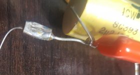
Other two smaller yellow circles are simply cramped metal tubes for connecting wires. The orange thing parallel to the yellow 2.2 uF capacitor should be capacitor too, but the printed value is not visible. Desolder it and take a picture of the printed values.I need helps Specifically with those encircled in yellow.
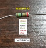
Resistors are arranged as a L-pad for attenuating the tweeter, but their wattage are too small.
I have a pair of 0.5s somewhere in the shed/loft.
One stopped working after a loud pop when I was inserting a cable somewhere in the pre amp. Investigation revealed the same 1/4 Watt size resistors. One of these had gone open circuit and saved the tweeter. once replaced with the same value everything was fine.
Consequently I think they were this size on purpose, and they should at least sound good with low inductance. Consider that Heybrook often used 1st order on tweeters at frequencies around 3-5Khz, so a simple L pad for attenuation/protection and 2.2uF Yellow capacitor in parallel with orange polyester capacitor my guess (0.1uF-0.47uF) to give the necessary 1st order crossover point.
As you know one resistor is 2.7 ohm do you have a digital voltmeter/ohmmeter to measure their values, possibly you may find one is open circuit, if not the ohmeter should allow you to confirm the values.
Stick with it, they are enjoyable speakers, probably mounted near or up against a wall to get a bit more bass weight.
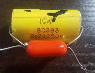
2.2 microFarads capacitor, 250 V, MKT or MKP.
Thanks! The manufacturer (ICW) got back to me with the following:
"May we suggest you take a look at our PX range. I have attached a copy of our datasheet.
You will note there is a slight difference in the dimensions being 30mm Long x 22mm Width when compared to part SC393 being 33mmLong Max x 19mm Width.
The original drawing for part SC393 was created back in 1987.
It looks as though the customer at that time asked for specific dimensions hence the 'SC' number allocated to the part which highlights a product has special customer requirements. Also, when a part deviates from a standard product."
I have a pair of 0.5s somewhere in the shed/loft.
One stopped working after a loud pop when I was inserting a cable somewhere in the pre amp. Investigation revealed the same 1/4 Watt size resistors. One of these had gone open circuit and saved the tweeter. once replaced with the same value everything was fine.
Consequently I think they were this size on purpose, and they should at least sound good with low inductance. Consider that Heybrook often used 1st order on tweeters at frequencies around 3-5Khz, so a simple L pad for attenuation/protection and 2.2uF Yellow capacitor in parallel with orange polyester capacitor my guess (0.1uF-0.47uF) to give the necessary 1st order crossover point.
As you know one resistor is 2.7 ohm do you have a digital voltmeter/ohmmeter to measure their values, possibly you may find one is open circuit, if not the ohmeter should allow you to confirm the values.
Stick with it, they are enjoyable speakers, probably mounted near or up against a wall to get a bit more bass weight.
Thanks! Yeah, I'm guessing one (or both) resistors are shot. No output from the tweeters. Was able to test the tweeters though with a 2-way crossover I had lying around and it was indeed working.
I was thinking of redoing the whole thing (caps and all) by getting components with matching values. Seems simple enough..... right? To be honest, I don't have much of a background in electronics.
Other two smaller yellow circles are simply cramped metal tubes for connecting wires. The orange thing parallel to the yellow 2.2 uF capacitor should be capacitor too, but the printed value is not visible. Desolder it and take a picture of the printed values.
Resistors are arranged as a L-pad for attenuating the tweeter, but their wattage are too small.
Oh OK... Those silver things had me stumped. Thanks. Are they necessary though?
Update:
Are my resistor values correct? I just used an online resistor calculator. Don't know if I read it right though. I also just assumed that both are 1/4 watt from what everyone is saying...
Are my resistor values correct? I just used an online resistor calculator. Don't know if I read it right though. I also just assumed that both are 1/4 watt from what everyone is saying...
Attachments
Update again:
I'm learning as I go here... So yeah, both resistors are the same size. 6mm x 2mm.. so both should be 1/4W
I'm learning as I go here... So yeah, both resistors are the same size. 6mm x 2mm.. so both should be 1/4W
Yes, those values are right ( in the ballpark )
Read what Raymond wrote about their "fuse function" and about the design of the crossover ( simple cap on the tweeter and the woofer with natural/mechanical lowpass ) and the placement against the wall.
Read what Raymond wrote about their "fuse function" and about the design of the crossover ( simple cap on the tweeter and the woofer with natural/mechanical lowpass ) and the placement against the wall.
Yes, those values are right ( in the ballpark )
Read what Raymond wrote about their "fuse function" and about the design of the crossover ( simple cap on the tweeter and the woofer with natural/mechanical lowpass ) and the placement against the wall.
Great, thanks so much!
😛I was to say that I would at least have used 2 W resistor, which is the maximum in that "package". However, you can use 10 X 27 Ω 1/4 W in parallel, but the purpose is to have a fuse. Indeed, a 2 W might darken and then burn, but not blow (interrupt) instantly when max power is surpassed.
that is to say, usually you find 5 W ceramic or even 20 W in certain crossovers ( like a "Q damper" at the leg of a capacitor, after the coil in a lowpass filter for correcting the "slope" )
and oh! I was to say that the orange cap in parallel might be negligeable.
You can bring out of box the tweeter connections and arrange the crossover outside.
Bi-wiring from the amplifier is possible.
You can even wire the tweeter path with thinner wire...till it fuses!
Or use graphite blocks to make resistors eh eh
Last edited:
😛I was to say that I would at least have used 2 W resistor, which is the maximum in that "package". However, you can use 10 X 27 Ω 1/4 W in parallel, but the purpose is to have a fuse. Indeed, a 2 W might darken and then burn, but not blow (interrupt) instantly when max power is surpassed.
that is to say, usually you find 5 W ceramic or even 20 W in certain crossovers ( like a "Q damper" at the leg of a capacitor, after the coil in a lowpass filter for correcting the "slope" )
and oh! I was to say that the orange cap in parallel might be negligeable.
You can bring out of box the tweeter connections and arrange the crossover outside.
Bi-wiring from the amplifier is possible.
You can even wire the tweeter path with thinner wire...till it fuses!
Or use graphite blocks to make resistors eh eh
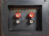
Thanks for the advise. I will post a rough diagram of the existing network in a bit. I'd like to know whether I should just go ahead and match up all the values or perhaps change some components. Yes, it seems the speaker is designed to be bi-wired. I'll post a picture of the speaker terminal which shows this.
So I made a rough diagram of what the network currently looks like. Thanks to all those who answered my questions. My apologies for being such a noob. 😀
Anyway, I'd just like to hear your thoughts about what parts I can replace them with. Fire away!
* BTW, Attached a pic of the speaker terminal as well as the code for the orange capacitor.
Anyway, I'd just like to hear your thoughts about what parts I can replace them with. Fire away!
* BTW, Attached a pic of the speaker terminal as well as the code for the orange capacitor.
Attachments
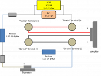
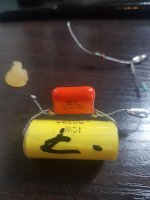
The orange capacitor is 33 nanoFarads (0.033 microFarads), 250 V, MKT or MKP.
Keep both capacitors (yellow and orange), they are fine. Change only the resistors with a new ones.
Keep both capacitors (yellow and orange), they are fine. Change only the resistors with a new ones.
No, just simply solder the wires together.Those silver things had me stumped. Thanks. Are they necessary though?
The orange capacitor is 33 nanoFarads (0.033 microFarads), 250 V, MKT or MKP.
Keep both capacitors (yellow and orange), they are fine. Change only the resistors with a new ones.
No, just simply solder the wires together.
Awesome. Thanks!
Repair done! I wasnt able to take any pictures since I was in a bit of a rush. I'd just like to thank everyone who took the time to answer my questions. Again, thank you! And yeah, just had to replace the 2.7ohm resistor.
Oh, and these things actually sound very good to my ears. Haven't had many speakers but am definitely liking these.
Oh, and these things actually sound very good to my ears. Haven't had many speakers but am definitely liking these.
- Status
- Not open for further replies.
- Home
- Loudspeakers
- Multi-Way
- Help needed: Crossover for Heybrook Point Seven