After just restoring my "Electrocompaniet The 2 channel preamplifier" it's now time to restore the amplifier.
What I'm looking for is some photos and assembly instructions of the internal, of the original "Electrocompaniet
The 2 channel amplifier" from about 1978.
I would like to rebuild my one that's I decided to dismantle about 20 years ago which was a fatal mistake.
I now need to make a new case and some new PCB's as these parts have gone missing all that I can find
from the original amp is the transistors, transformers, heat sinks and front panel.
msdin
What model Electrocompaniet amp is that? Do you have the service manual with circuit diagrams (schematic) and knows how to draw PCBs and make them? And what PCBs you need to remake?
I meant no offense but from what you are saying what's left from that amp, it's probably better to buy another used one than rebuilding it. It'll be a very long winding road since you don't even have the side panels or the top cover to make it look like what it was 20 years ago. 🙂
I meant no offense but from what you are saying what's left from that amp, it's probably better to buy another used one than rebuilding it. It'll be a very long winding road since you don't even have the side panels or the top cover to make it look like what it was 20 years ago. 🙂
The amplifier was the original 25 Watt Class A model circa 1978. I have a set of schematics for the amplifier but no information for the PCB's. The layout was critical so to prevent it from oscillating. If I could find some pictures of the inside I would remake the parts that I missing. I' also have no problem with making new PCB's as I have all the kit to make one-offs.
Hi
I see that you have restored The 2-Channel Preamplifier - I need to do that, too! Do you have any suggestions, schematics etc. to share? I am a little desperate...
I see that you have restored The 2-Channel Preamplifier - I need to do that, too! Do you have any suggestions, schematics etc. to share? I am a little desperate...
Hi
I see that you have restored The 2-Channel Preamplifier - I need to do that, too! Do you have any suggestions, schematics etc. to share? I am a little desperate...
I can help you repair you preamp what is it doing or not doing? 🙂
Please PM me; I my be able to help you with some further information.
Hi Msdin
If its power amp details I can probably help out. I rebuilt one several years ago. Still have most info.
Tall order though but it can be done.
Tony
If its power amp details I can probably help out. I rebuilt one several years ago. Still have most info.
Tall order though but it can be done.
Tony
Power amps
Hi Tony,
Many thanks, I’ve some information from the net, and although both amps are working, the temperature achieved by each is different on the channels, if that makes sense. I was going to swap out the old 1k and 220R pots for some new bournes, but just wanted to make sure I could reset the bias and offset, hoping this would get them more uniform. I’ve downloaded Sharifs post but just needed to identify the points correctly before starting. His preamp is much different to mine and I wondered if the power amp boards would probably be different too.
Kind Regards
Joe
Hi Joe
If I've understood this is how I used to setup
Bias
Check voltages across R34 R35 R36 R37 emitter resistors to give approx 500mv.
Adjust with 1K pot.
Dc offset
Connect meter leads into speaker output.
Adjust with 220R pot
You can increase the bias voltage across emitter resistors but beware of heat build up which was the achilles heal of this amp.
Tony
Hi Tony,
Ok just so I’ve got it, connect the DMM across both ends of those resistors?
So not using the a,b,c,d points on the photo?
Thanks for your time
Joe
Ok just so I’ve got it, connect the DMM across both ends of those resistors?
So not using the a,b,c,d points on the photo?
Thanks for your time
Joe
Hi Tony, well a small measurement of success with one of the amps anyway. I managed to find the extra info that mentions reducing the bias to 400mV after the 1hour and the amp responded well to this - the fins about 50/55c after an hour. Im still not too happy with the cooling arrangements as the slots in the base panel are too far away and so I'll put some smaller holes in the bottom, in the space between the boards and the heatsinks. This hopfully will work like a radiator against a wall.
The second amp was/is a problem. No bias current at all on one channel. ( this amp did however produce sound from both channels when I last checked it!). The 1K pot made no difference and when I removed it it was u/s. So I replaced this and a couple of other components ( carbon resistors) while I was at it. Theres also quite a lot of through board connections so I remade all of these with a small piece of wire in case age and corrosion were having an effect. The other board worked and could be set. But on adding this reworked board I noticed the power transistors were very hot and then nothing, no bias on either board. So I imagine the protection circuit kicked in. Which leads me to speculate theres still a problem with that board. If you've any suggestions I'm all ears. I have BCY87 & 89, plus diodes, so can check these.
One thing could you let me know how your Power transformers run across the top of the board - , I have ( I think), BD139, BD139, BD139, BD140, BD203, BD203, BD139, BD204, BD204 - going left to right across the top.
Thanks in advance
Joe
Hi Joe
Plot thickens.
First off transistor lineup is from (L-R)
Q8 Bd139
Q9 Bd139
Q5 Bd140
Q6 Bd140
Q7 Bd139
Q10 Bd139
Q11 Bd140
Q12,Q13 Bd203
Q14,Q15 Bd204
I suspect they are Ok if you have previously had sound.
But check as a first step.
Next thing to do is make sure which channel is giving trouble.
Unplug the board connector to one channel and switch on. Any defect should kick in causing the protect cct to operate and the led on front panel to blink. Now replu and repeat for other side. I know you know which channel is defunct but just do this check to see if protect works.
Hi Tony
Thanks for the reply,
I’ll get on that tomorrow and get back to you with the results as I’ve 1/2 the garage out in the drive at the moment 😊
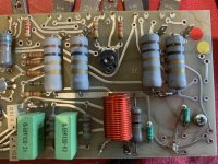
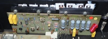
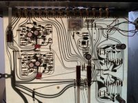
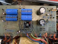
Just to check the transitory along the top here’s my boards which are different to any published schematic.
Are they the same layout as yours?
Thanks again
Joe
Thanks for the reply,
I’ll get on that tomorrow and get back to you with the results as I’ve 1/2 the garage out in the drive at the moment 😊
Just to check the transitory along the top here’s my boards which are different to any published schematic.
Are they the same layout as yours?
Thanks again
Joe
Attachments

- Home
- Amplifiers
- Solid State
- Help need for Electrocompaniet The 2 channel amplifier