Hello,
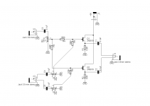
I'm going to build a Fet audio mixer which can mix a mono signal from a guitar/bass/other instruments with a PC/Ipod/other music source. I have looked in the net, and couldn't find anything that suit my need. So, I made this schematic which I followed from this site FET Audio Mixer
Can anyone see if my schem is correct or wrong ?
Thx
Abner
Attachments
I see one concern, plus two potential concerns.
1. Concern: the A.C. Coupling capacitors are too small relative to the nominal 10K ohm pots. at the input side. They are likely too small on the output side as well, depending on the load being driven. These caps. should be more on the order of 1uF, or the mixing resistors and level pots. increased by that same factor of ten or so.
2. Potential concerns: Can the sources drive the net sub 10K ohm input impedance with low enough distortion? Will those JFET followers drive the net sub 8.6K ohm output impedance with low enough distortion?
You could alternatively build an op-amp based mixer which might be D.C. coupled (no coupling caps.) and which could drive a relatively low impedance load with low distortion. Of course, if you adverse to loop-feedback circuits then stay with the JFET follower you have here.
@Ken: Thx for ur reply.
I'm a noob in electronic, so I can only modified someone's schem so I don't know about the caps/rest values being not good.
What if I put 1uF caps, 10k rests and 10k pots on the input side? And 10uF caps on the output side ?
What value do you think is good for the net sub output impendance ?
What should I use, polarized or non-polarized caps ?
I'm not adverse opamps, it's just that opamps schem's abit complicated for my 1st project..but eventually I will get there, coz I'm thinking to make other projects 😛
Go ahead and try 1uF (or larger coupling) caps. with the 10K level potentiometers and 100K mixing resistors shown in your schematic. You can try using the same capacitor for the output coupling as well. I don't recommend using electrolytic capacitors, whether polarized or non-polarized, for audio signal coupling purposes. Use a Mylar or Polypropylene film type instead. Parts Express sells decent film caps for not much money. Don't buy any exotically priced caps. for your first project.
Don't worry about the net impedance seen by the JFETs for now. A later revision could be to replace those 6.8K source resistors with an active JFET current-source load. To see an example, search for Nelson Pass' DIY JFET line buffer project. You basically would be combining Nelson's JFET buffer circuit with your resistor input side mixing circuit.
Good luck with your project. Let us know how it comes out.
Ok, I've tested the schem with a testboard. Using 1uF coupling caps, no pots, 10k ohm resistors. I put 10uF on the output coupling.
The output is really low and distorted...so what's the problem here ? what value to change ? I Tried 100k, 200k, and 470k and the output getting louder but distorted.
The output is really low and distorted...so what's the problem here ? what value to change ? I Tried 100k, 200k, and 470k and the output getting louder but distorted.
I just now had a second look at your schematic and noticed on obvious error I should have noticed before. Those 6.8K resistors connected to the JFET source terminals are then connected to ground. They instead be connected to a negative supply, which means a second -9V power rail giving a bipolar power supply. The distortion is due to signal clipping because insufficient voltage swing is available across the source resistors.
If you measure the D.C. bias voltage from the JFET source terminal to ground you will probably find it to only a few hundred millivolts or so. There needs to be enough bias voltage across those resistors to handle the full peak signal amplitude. Adding a 9V negative supply will produce a bias current of just over 1mA through those 6.8K resistors values.
If you measure the D.C. bias voltage from the JFET source terminal to ground you will probably find it to only a few hundred millivolts or so. There needs to be enough bias voltage across those resistors to handle the full peak signal amplitude. Adding a 9V negative supply will produce a bias current of just over 1mA through those 6.8K resistors values.
hmm. then I must make a power supply 1st then.
I prefer to use a wallwart power supply. Is there a better schem which use a single positive supply only ?
I prefer to use a wallwart power supply. Is there a better schem which use a single positive supply only ?
Yes, there is a way. I suggest adapting the Pass B1 DIY design for you project, which uses a single 18V supply. Keep the summation (mixing) network section of your original design and connect that to the left side of the D.C. blocking capacitors feeding the JFET gates. Then, from the right side of those blocking caps. forward utilize the active section of Pass' B1 as designed after those blocking caps.
http://www.passdiy.com/pdf/B1 Buffer Preamp.pdf
http://www.passdiy.com/pdf/B1 Buffer Preamp.pdf
- Status
- Not open for further replies.
- Home
- Design & Build
- Construction Tips
- Help me with this FET audio mixer