Is the grounding correct on this power supply, or do I need a star ground?
It will be used as a power supply for an active filter in an active subwoofer, and I wonder if it will do the job, or do I need something more complex? It will be used to power two opa2134's.
C1,C2=4700uF elec.
C3,C4,C5,C6=100nF Polypropylene
C7,C8=100uF elec.
R1,R2=220R
R3,R4=2k94
It will be used as a power supply for an active filter in an active subwoofer, and I wonder if it will do the job, or do I need something more complex? It will be used to power two opa2134's.
C1,C2=4700uF elec.
C3,C4,C5,C6=100nF Polypropylene
C7,C8=100uF elec.
R1,R2=220R
R3,R4=2k94
Attachments
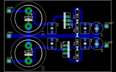
Hi there........youre doing fine.......a wise bet would be to really beef up the ground tracking especially around the 4700uF filter caps where the commons join. This is where peak currents flow. Common wisdom dictates all ground related layouts be physically made massive and IC bypass caps be physically close to devices.
Remember IC's are also amps, and will oscillate with poor layouts.
The o/p track layout be also thick to take advantage of the low Z impedance. The earthy junctions of R2/4; C7/9;C3/5 should be as short as possible to take advantage of the good PSRR. (power supply ripple rejection)
rich
Remember IC's are also amps, and will oscillate with poor layouts.
The o/p track layout be also thick to take advantage of the low Z impedance. The earthy junctions of R2/4; C7/9;C3/5 should be as short as possible to take advantage of the good PSRR. (power supply ripple rejection)
rich
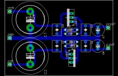
I might be wrong but this is how I would do it if I had to. I know that two opa2132 will probably require less than 80mA total, but still, fatter traces are easier to make at home and will give you enough headroom even if the transfer/etching process goes wrong.
Sébastien
Sébastien
Attachments
A PSU I was trying to build: comments?
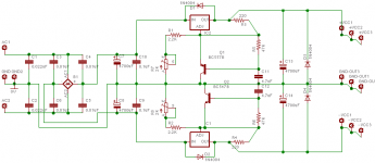
I was trying to "design" a PSU, by putting together two circuits from Randy Slone's Audiophile Projects book. Here's the schematic. It uses LM317/337 for regulation, and uses a high-gain transistor at the ADJ pin of each for making the regulation more sensitive. My schematic keeps only the transformer outside the PCB, and mounts all other parts on the PCB. I guess the circuit will be good for upto about 1A in each leg? That should see me through quite a large set of active xo and preamp and what have you.
Any comments? I'm new, so please point out mistakes.
Tarun
Attachments
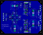
And the PCB for it...
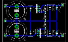
And I designed the PCB for this thing, in Eagle. Will the layout work? Any tips on PCB design?
I kept two ground terminals on the input side, to allow both leads from a toroidal transformer to come in; normal E+I transformers seem to have just one lead for the centre tap. I also kept three-of-each terminals on the output side, so that up to three different PCBs could easily draw power from this board, without having to do messy wire splicing. In the local market, I get screw-tightened terminal blocks with legs spaced 0.2" apart. I intend to use those for the input and output connections. I've used vertical multi-turn pots for the voltage adjustments... don't know if that's overkill. There's one short jumper, carrying one of the supply rails, near IC1 at the bottom. Couldn't avoid it easily. Though the PCB therefore looks double-sided, I've decided to use a piece of wire for that lead, and make it single-sided.
Comments please. I can't go ahead and make it till I hear from you guys. Don't know what goofups I've made.
Tarun
Attachments
TCPIP has it right
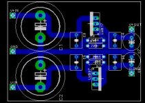
You need separate ground points for the input side, the transformer and the output side so that none of the capacitor charging pulses are seem by the output. And you need fat grounds.
You need separate ground points for the input side, the transformer and the output side so that none of the capacitor charging pulses are seem by the output. And you need fat grounds.
The manual tells you how
Then, draw the polygon. And after that, click on the "name" icon (to change the name of an object), then select the polygon, and set the name of the polygon to be the same as the signal you want it to merge with. Eagle will pop up a box asking you what the merged name will be? Two choices will be shown: the name you want to merge with, and the system-generated name of the polygon. You can select either one, I guess, though I always select the name of the signal (e.g. "GND") I want to merge with. And Eagle will then do the rest.
I've also discovered something else the hard way, which you may not know, if you're as much of a novice as I am. Polygons can't overlap. If they do, the rendering will be fine, but the DRC will always scream about clearances. If you like to have a clean DRC (I find it useful), then keep polygons non-overlapping.
A third thing I've discovered about Eagle is that the standard devices in the parts library usually have pads with restrings which are too narrow for easy fabrication. It's possible that when the PCB is made, you'll have insufficient soldering area around the holes in some of the pads. To increase the pad restring annular radius, click on the "Restring" tab in the DRC dialog box, and set the minimum restring radius from 10mil to something like 18 or 20mil. That'll automatically make all pads on your layout swell out. Then go check the PCB with a fine-toothed comb to ensure that nothing's shorting. (For instance, after you set the minimum restring for pads to 20mil, you may not have enough space left over to pass a track through two legs of a DIP IC. Bother!)
Hope this helped. Sorry if I overloaded you with stuff you already knew. All this is very very recent knowledge for me, so I'm excited. 😀
And BTW, like all my other "Designs", you're free to pick up any of the design files, Eagle files, whatever, for anything I'm doing, and do whatever you want with it. I don't treat any of my work in diyaudio as proprietary or private. 🙂
You use the "show" command or the "info" command (the one with the small "i" on its button) to identify the signals to which you want to connect the polygon. This will show you the signal name. This name could be something readable like "GND" or something system-generated like "N$13".Alcaid said:How do you connect parts to the polygon i Eagle? I only get totally isolated polygons.
Then, draw the polygon. And after that, click on the "name" icon (to change the name of an object), then select the polygon, and set the name of the polygon to be the same as the signal you want it to merge with. Eagle will pop up a box asking you what the merged name will be? Two choices will be shown: the name you want to merge with, and the system-generated name of the polygon. You can select either one, I guess, though I always select the name of the signal (e.g. "GND") I want to merge with. And Eagle will then do the rest.
I've also discovered something else the hard way, which you may not know, if you're as much of a novice as I am. Polygons can't overlap. If they do, the rendering will be fine, but the DRC will always scream about clearances. If you like to have a clean DRC (I find it useful), then keep polygons non-overlapping.
A third thing I've discovered about Eagle is that the standard devices in the parts library usually have pads with restrings which are too narrow for easy fabrication. It's possible that when the PCB is made, you'll have insufficient soldering area around the holes in some of the pads. To increase the pad restring annular radius, click on the "Restring" tab in the DRC dialog box, and set the minimum restring radius from 10mil to something like 18 or 20mil. That'll automatically make all pads on your layout swell out. Then go check the PCB with a fine-toothed comb to ensure that nothing's shorting. (For instance, after you set the minimum restring for pads to 20mil, you may not have enough space left over to pass a track through two legs of a DIP IC. Bother!)
Hope this helped. Sorry if I overloaded you with stuff you already knew. All this is very very recent knowledge for me, so I'm excited. 😀
And BTW, like all my other "Designs", you're free to pick up any of the design files, Eagle files, whatever, for anything I'm doing, and do whatever you want with it. I don't treat any of my work in diyaudio as proprietary or private. 🙂
Totally OT...
... but where is Stavanger? And about helping you, you're most welcome. 🙂 I still can't believe I'm actually of help to anyone on this forum. 😀 Everybody gives me such a complex. 🙂Alcaid said:Thanks for helping me, tcpip! 🙂
- Status
- Not open for further replies.
- Home
- Amplifiers
- Solid State
- Help me with my PSU PCB