Hello,
I would like to ask an help to all the experts in tube amp, particularly in SETs.
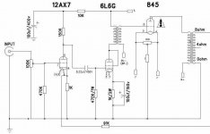
I have a Dared VP-845, which I frequently use with my AKG K1000 ear speaker. Since K1000 have impedance of 120hm, it is often said that high damping factor or at least adjustable negative feed back amp works best with them. I would like to know what parts in the schematic I can play with to achieve damping factor for this 845SET best suited for K1000. ( except the output transformer)
Specifically, the schematic shows 91K connected from 8 ohm tab of output transformer to the cathode of 12AX7. Is this some sort of negative feed back?
Thanks!
-John
I would like to ask an help to all the experts in tube amp, particularly in SETs.
I have a Dared VP-845, which I frequently use with my AKG K1000 ear speaker. Since K1000 have impedance of 120hm, it is often said that high damping factor or at least adjustable negative feed back amp works best with them. I would like to know what parts in the schematic I can play with to achieve damping factor for this 845SET best suited for K1000. ( except the output transformer)
Specifically, the schematic shows 91K connected from 8 ohm tab of output transformer to the cathode of 12AX7. Is this some sort of negative feed back?
Thanks!
-John
Attachments
John :
General answer
The 91K resistor is indeed the feedback resistor. Lowering the value will increase feedback, decrease gain, decrease output resistance and thus increase damping factor. But if you lower the resistor too much you may get instability. Try some different values and see (hear) what happens.
Specific to your situation
But, having said all that, you say you want to lower damping factor in order to best suit some 120 ohm headphones. If so, I must assume you have some sort of attenuating/matching resistors between the amp and the headphones. 1) so the amp sees 8 ohms, not 120, and 2) to reduce the power to the headphones so you dont go deaf. If that is the case then, the attenuator network predominates and sets the source impedance that the 120 ohm headphones sees, and the output resistance of the amp will make very little difference to the damping factor.
Of course you may still want to play with the 91K resistor to change feedback for other reasons, such as distortion reduction.
May be change the transformer
May be You need to change the output transformer.
And understand what kind of demping factor do you need.
Dempoing is the Alfa (Ra/R out)
Both amps maker calculated Alfa 3-5,
Some-times it's 6-7...
I am prefer mopre than 10...fery offten 26-30 Alfa
If recalculate its more than 3 or 15 parts.
Feedback have a time delay and bring dirt in a sound and compression is signal.
Than impedanse low in secondary than demping better like the force for push the speaker and stop it. And sound more concret.
Thanks for the replies.
The AKG K1000 is designed to be driven directly bfrom speaker amp. No resistor network. so the name earspeaker. They have very low, 74dB efficiency, but one of the best dynamic headphone around. My amp supposedly output 22W, and my volume is about 30-40% using it.
Regarding the negative feedback, I'm not sure the following thinking is correct, bieng a real noovie... Since K1000 impedance is 120ohm, I don't need as much of damping factor (or as low amp output impedance) as speakers. So I can have lower negative feedback (for clearer sound) and stable operation.
If this is right, based on your experience, how high resistance would you expect I could replace 91K with before I will be running into stability issue?
Also do I need to change the bias current to 845, when I change the negative feedback?
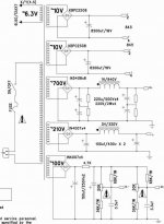
You forgot to post the part of the schematic that has the largest impact on an amp's damping factor --- The Power Supply ---
You can always try to play games with feedback, but if the power supply can't supply the demanded current the tube is asking for all the calculations in the world will not help. More than likely your amp has a high impedance power supply. The result is flabby uncontrolled bass and poor dynamics.
You can always try to play games with feedback, but if the power supply can't supply the demanded current the tube is asking for all the calculations in the world will not help. More than likely your amp has a high impedance power supply. The result is flabby uncontrolled bass and poor dynamics.
John,
you also might get stability issues with "global" feedback in such a design, means around two transformers. It can work, but I would definetly check the phase shift before trying to implement such a feedback loop. An alternative might be local feedback around the 845.
Marcus
you also might get stability issues with "global" feedback in such a design, means around two transformers. It can work, but I would definetly check the phase shift before trying to implement such a feedback loop. An alternative might be local feedback around the 845.
Marcus
Hoops, sorry, just saw that the "instability issue" was stated before already... never mind!
Marcus
Marcus
rdk845 said:Right. Here it is.
What is the operating point for the 845? Vp, Ip, Vg? Also, if possible could you tell me what the DCR of the 1H choke is, and the 700V winding for the power transformer. Lastly, is this a mono block, or does this one power supply feed both channels?I'll see what I can come up for you.
O.K. I may not have answer for some of these parameters.
845 Plate voltage seems to be ~ 850V.
The biass current is currently set to be ~ 70mA. The factory set would be more like 100ma, based on 22W per channel rating. I reduced them, since I'm currently using 845W which has probably lower dissipation current rating than Shuguang, and also I don't need high power for K1000.
I think the 845 grid voltage is ~120V.
I don't have DCR of the chokes and tranny winding, but I guess I could measure them, if they are important. Do I just desolder connection and measure the DC resistance?
Thanks.
The AKG K1000 is designed to be driven directly bfrom speaker amp. No resistor network
OK, I think I understand no need for attenuation due to low efficiency. But if the impedance of the ear speaker is 120 ohms, and you are connecting it to the 8 ohm tap of the op transformer then the load line is going to be radically changed from what the amp designer expected. In fact by a factor of 15. I dont know personally what the optimum load for a 845 is, but I would think the original design wouldnt be off by a factor of 15. I could be wrong about this, your ears will tell you.
Actually its the other way around, lower resistance ( ie more feedback) may give stability problems. You dont know what margin of stability has been designed into this thing unless you test it by swapping in lower resistors and testing what happens. My guess ( perhaps optimistic) would be you could cut the value in half, ie it has at least 3dB margin.how high resistance would you expect I could replace 91K with before I will be running into stability issue?
I would rephrase that slightly, given a 120 ohm speaker, your amp could have 15 times higher output impedance and you would still have the same damping factor as the original amp with 8 ohm speakers. Or since you are using the same amp, you have improved damping factor by using the higher impedance speaker.Since K1000 impedance is 120ohm, I don't need as much of damping factor (or as low amp output impedance) as speakers
Yea, I don't understand it either, but K1000 performs best with speaker amp, particularly with tube amps. A well known fact to people in i.e. headfi.but I would think the original design wouldnt be off by a factor of 15. I could be wrong about this, your ears will tell you.
So I could really increase the feedback resistance like to 1M ohm and it would stil be stable? I guess I would try reducing the resistance just to see how it sounds but,, wouldn't decreasing the feedback (increasing the resistance) be more desirable sound quality wise?Actually its the other way around, lower resistance ( ie more feedback) may give stability problems
Operation point
Hi JLH,
I did some measurements and here they are.
845 Plate voltage : 873-4V
Bias Current : 70mA
Grid Voltage : -125 (R) -130(R)
The DC resistance of the 700V wiring on the power transformer is 19.4Ohm
The DC resistance of 1H choke is 14.7 ohm.
Hope you can get some data out of these.
Thanks for your help!
-John
What is the operating point for the 845? Vp, Ip, Vg? Also, if possible could you tell me what the DCR of the 1H choke is, and the 700V winding for the power transformer. Lastly, is this a mono block, or does this one power supply feed both channels?I'll see what I can come up for you.
Hi JLH,
I did some measurements and here they are.
845 Plate voltage : 873-4V
Bias Current : 70mA
Grid Voltage : -125 (R) -130(R)
The DC resistance of the 700V wiring on the power transformer is 19.4Ohm
The DC resistance of 1H choke is 14.7 ohm.
Hope you can get some data out of these.
Thanks for your help!
-John
I woke up in the middle of the night and realized " wait a minute, higher impedance, flat load line, less power ... " and for head phones that is exactly what you want. Being a triode , you dont have to worry about keeping the load line above the knee in the plate curves as you do with pentodes. So I think I am starting to like the 120 ohm ear speaker idea.
You could take it off completely and it would be stable. It would be running open loop. You would get the maximum amount of gain out of it, you will have to reduce the input level accordingly to avoid clipping.So I could really increase the feedback resistance like to 1M ohm and it would stil be stable?
That is the great debate. Increasing feedback (decreasing resistance) will reduce harmonic distortion, and if you go by numbers that is a good thing. But some people like a "tube" sound, whatever that may actually be, and may prefer a bit of 2nd harmonic distortion, so they would like less feedback.wouldn't decreasing the feedback (increasing the resistance) be more desirable sound quality wise?
Re: Operation point
Much to my surprise your power supply was not as bad I thought. However, I think there is a small modification you can do to lower the power supply's impedance, make it behave better, and make it easier on the rest of the amp.
I simulated your factory power supply in PSUDII. Below are the results. The first thing you should notice is how poorly dampened the factory supply is. The peak voltage at turn on is quite high and does no favors for the tubes. Power supply ripple is pretty low, which is a good thing. The power supply impedance was much lower than I expected. I was expecting something in the 300 ohm range.


Now it is time for some improvement. I'm not sure how comfortable you are making this modification, but would encourage you to try it. I would move the first set of 220uF caps and balancing resistors to after the factory 1H choke. This will make your final cap reservoir 220uF. Put a Hammond 159ZJ choke right after the bridge. Next put a 40uF 660VAC motor run cap between the 159ZJ and the 1H factory choke. This will make your supply a LCLC. Now look at the improvement this supply will make over your current one. This modification will only cost you about $35 dollars in parts.


As you can see the modified power supply is much better behaved. It has the same output voltage. It does have a little bit more ripple, but will make no difference with a low Mu tube like the 845. The big thing is no more voltage bounce at turn on. That turn on behavior is just nasty on the factory power supply. Hopefully this will help your amp if you choose to make the modification.
Rgs, JLH
rdk845 said:
Hi JLH,
I did some measurements and here they are.
845 Plate voltage : 873-4V
Bias Current : 70mA
Grid Voltage : -125 (R) -130(R)
The DC resistance of the 700V wiring on the power transformer is 19.4Ohm
The DC resistance of 1H choke is 14.7 ohm.
Hope you can get some data out of these.
Thanks for your help!
-John
Much to my surprise your power supply was not as bad I thought. However, I think there is a small modification you can do to lower the power supply's impedance, make it behave better, and make it easier on the rest of the amp.
I simulated your factory power supply in PSUDII. Below are the results. The first thing you should notice is how poorly dampened the factory supply is. The peak voltage at turn on is quite high and does no favors for the tubes. Power supply ripple is pretty low, which is a good thing. The power supply impedance was much lower than I expected. I was expecting something in the 300 ohm range.
Now it is time for some improvement. I'm not sure how comfortable you are making this modification, but would encourage you to try it. I would move the first set of 220uF caps and balancing resistors to after the factory 1H choke. This will make your final cap reservoir 220uF. Put a Hammond 159ZJ choke right after the bridge. Next put a 40uF 660VAC motor run cap between the 159ZJ and the 1H factory choke. This will make your supply a LCLC. Now look at the improvement this supply will make over your current one. This modification will only cost you about $35 dollars in parts.
As you can see the modified power supply is much better behaved. It has the same output voltage. It does have a little bit more ripple, but will make no difference with a low Mu tube like the 845. The big thing is no more voltage bounce at turn on. That turn on behavior is just nasty on the factory power supply. Hopefully this will help your amp if you choose to make the modification.
Rgs, JLH
Great!
I will first try out with some negative feedback resistor values based on the suggestions and then check out the power supply mod as instructed
Thanks for all the input!
-John
I will first try out with some negative feedback resistor values based on the suggestions and then check out the power supply mod as instructed
Thanks for all the input!
-John
- Status
- Not open for further replies.
- Home
- Amplifiers
- Tubes / Valves
- Help me to work on the damping factor of my 845 SET