Probably something else still wrong besides gate drivers (but first place I would have checked). Diodes Inc. are my go-to devices for drivers, although I would have stuck in their old E-line parts in place of giant TO-92’s (With pin out change). My old Sanyo giant TO-92’s got discontinued too. The little bitty E-lines and SMDs are fine for switching duty, not so good when you need that 900mW dissipation.
E-line are specifically designed for higher dissipation than TO92, that's why they have a larger flat area for mounting against a heat-sink, bth sides are flat, are thinner to reduce the amount of epoxy between die and case surface, and can be soldered flush against a PCB for maximum thermal conduction to the PCB traces.
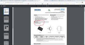
For instance ZTX851 rated at 1.2W free, or 1.58W with 1 square in of copper PCB plane to spread heat.
For instance ZTX851 rated at 1.2W free, or 1.58W with 1 square in of copper PCB plane to spread heat.
70 kHz isn’t very high - I doubt even a regular TO-92 would even heat up. Gate drive power is CV^2f. But you want a high hFE at a couple of amps for a few tens of to maybe a hundred ns at a time, so the 2N3904 need not apply for the job.
Thanks guys.
This time i will replace more parts,like the NTC 901,rectifier,D913,all the snuber diodes(D911,905),. and caps C941,945,all the gate diodes D903,909,Resonance cap C922,all the electrolytics C906,910,913,917,BUT for drivers,i'm afraid that i'm at a dead end again?😢
Is it necessary the PNP AND NPN driver belongs to the same hfe grade?
I ask this because i can find ZTX790B availabe but only ZTX690A.
Same for FCX790A & FCX690B. Last combination would be the best for me as they are available at Mouser.
Last edited:
Just now i see this.
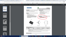
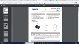
Theese are Complementary pairs and available at Mouser.
Application -Power MOSFET & IGBT Gate Driving
The one that i have on hand are special designed for the job but i don't know if these are suitable in my case.
https://gr.mouser.com/ProductDetail/ROHM-Semiconductor/RGT40TS65DGC11?qs=QkPn6D1Vh3jrPGFRkdViBA==
Attachments
Last edited:
ZTX749/690 is my universal “2 amps and under” driver set. Been using them for decades.
Not necessary for hFE to match. Most of the time you charge through a resistor and discharge through a diode, to force the mosfet/IGBT turn OFF time to be faster even if the NPN driver has more gain. That prevents cross conduction. The series R value tells you how much peak current is needed (VGS/R). Discharge will try to draw more, but run out of gain. Thats ok as long as it’s faster overall. Total energy is the same in the charge/dischrage cycle (for a given vgs) - so the overall heat only depends on frequency, not the number of nanoseconds it happens over each time. Just the number of times per second. 70 KHz isn’t crazy high these days, I’m confident they won’t overheat driving normally-sized devices. Some of the really big ones need 8 or 9 amps - but we’re talking solar farm size inverters and 14,000 watt amplifiers. That stuff is way outside my wheelhouse.
I normally pull all the associated parts to see what’s died, even if I’m going to to a blanket replacement. You need to find the reason for IGBT failure. Not always obvious. Resistors that look fine can be open.
Last edited:
Thanks again!
Yes,this time i will measure or replace enything that is possible.
I hope that transformer is ok as i haven't a way to check.
As soon as devil is in the detail, i have look closer to IR2153.
Part list requirement is IR2153D, unavailable at Mouer.
What i have used is IR2153 from local supplier...
I see another problem here.
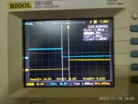
You should be able to set the front end to free run without the IGBTs installed, and make sure what’s going into the drivers is what’s expected. Complementary waveforms with what should be a small dead zone. That will rule out IC problems. They either work or they don’t.
You can and always should check a transformer. At LEAST for a primary to secondary short. If there is sign of overheating I’d pull it and make sure there are no shorted turns (Hit it with a sig-gen at 100kHz). Melty tape, discoloration, that sort of thing will trigger it. No sign of overheating i’d just trust my in-circuit ohm-out. Shorted turns normally result in INSTANT supply failure, so if it’s not instant chances are good it’s ok (Except for pri/sec short - which can kill you.)
If I have to spend more that a few weeks off and on jacking with an SMPS and Still havent found root cause, or if the transformer DOES have shorted turns it goes in the bin.
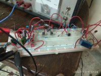
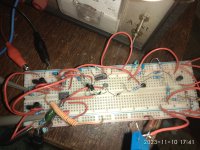
In the meantime i have this
A breadboard same circuit to study the purpose of each one of the transistors around the IR2153.
Scope at the drivers output
A breadboard same circuit to study the purpose of each one of the transistors around the IR2153.
Scope at the drivers output
Attachments

Last edited:
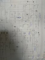
According to my findings
Q908 stop the oscillator when is active.
Q906 is a time delay circuit.
At startup delay the oscillator ,in compination with Q908 ,about 1".
Collector Q906 is positive and this positive voltage in Base of Q908 keep this active and IR2153 oscillator not working.
Q908 have a second role too.
This prevent the direct start after power off.
This time is about to 15".(C913 discharge)
Q909 is an overtemperature switch.
Two thermistors,one at the main heatschink and another one in the smps transformer keep the Q909 base positive as soon as temperature is low enough.
When temperature is high base go negative and this active the 909 and this active Q908 to stop the oscillator.
Q910 is an overcurrent switch
Current sense resistors Q919-920 monitor the IGPT current.
1.8 volt at point A about 3.6A is the maximum allowed current.
Attachments
Last edited:
I have seen so many reports about instant failures after startup in smps using IR2153.
One report say that is a very high frequency oscillation at startup.
I think this is the reason for use of the Q908.
Another reason for instant failure is the uncharged big electrolytics that is practically a short circuit for IGBT,that's why the NTC is in circuit.
Years ago PHONIC was selling a repair kit for this smps.
What was in the kit?
The drivers transistors,IGBT,small signal transistors,IR2153 AND the NTC.
I wonder why the NTC included in the kit?
As soon as NTC is something that anyone can measure cold and hot.
NTC never come in high temperature,in this circuit, because the relay short the NTC immediately after voltage presens at the secondary.
Can someone imagine a mystery NTC failure?
I ask this because my smps failed twice at start up and when no bulb connected in series with the main.
Last edited:
NTCs are physically quite fragile. I’ve seen my share of broken ones. And some with leads corroded off which resulted in overbiased conventional amps which used them alongside the bias diodes.
NTC in my case is clear,no crack no overtemperature signs.
I measured this when this is cold,ohmmeter indigate12 ohm at 25° celcius.
BTW in my previus repair attempts i used this IGBT. RGT40TS65DGC11
This IGBT (RGT40TS65DGC11),according to PDF, have built in very fast diode.
This smps have external fast clamp diodes D905,D911.
1)Is there a possibility that the existence of two parallel diodes creates a problem?
2)If you will find some free time,can you compare those IGBT,the( IRG4PC50W) and the (RGT40TS65DGC11).
I ask this because, if those aren't compatible ,that would explain the reason of unsuccessful repair.
Attachments
Last edited:
This Croatian guy still has those transistor if you can't find a good alternative.Any suggestion about drivers?
https://sansui-vintage.com/product/2sc2655-2sa1020-one-pair
/
On the input side, it looks like a MOSFET. On the output side, it looks like a bipolar transistor. IGBT is a monolithic device, If you want to read an authoritative tome on IGBT's, get The IGBT Device, by B. Jayant Baliga. ( can't shut the damn underline off!!)What is IGPT ? Thanks
IGBTs get used in switching supplies, and never caught on in any big way in audio amplifiers. IGBTs' key benefit is low ON resistance of the bipolar output section, a useful trait for high power switching applications. Their problem was relatively slow turn-off time, just like with bipolar transistors. As MOSFETs have gotten better by having low ON resistance while operating at the higher currents, as IGBTs can, the IGBT has lost ground to them in high power switching applications.
- Home
- Design & Build
- Parts
- Help me to find an IGBT alternative