im student in universty and i have homework about class d i need your help
f0= 1 kHz Vp = 1 V Vs= Vp(cos2pif0t) RL= 100 ohm PL= 1 W
i must design the circuit and simulate
this is may help for design
thank for your help
f0= 1 kHz Vp = 1 V Vs= Vp(cos2pif0t) RL= 100 ohm PL= 1 W
i must design the circuit and simulate
this is may help for design
An externally hosted image should be here but it was not working when we last tested it.
thank for your help
Last edited:
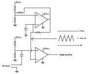
The "PWM modulator" could be designed with a couple of comparators.
One to generate the triangle waveform and one to compare that to the incoming audio to generate the PWM signal.
The "Preamplifier" could be just FET driver IC's, probably a low side FET driver and a high side FET driver.
The "switchgear with FET" could be a pair of n-ch MOSFET's.
The "Demodulator (LC filter)" is exactly that: LC low pass filter.
Look up and learn about all that is underlined and enjoy designing.
🙂
input is sinus signal and pwm for rectangle waveform demodulator for rectangle to sinus. but i dont know how we can do this allThe "PWM modulator" could be designed with a couple of comparators.
One to generate the triangle waveform and one to compare that to the incoming audio to generate the PWM signal.
The "Preamplifier" could be just FET driver IC's, probably a low side FET driver and a high side FET driver.
The "switchgear with FET" could be a pair of n-ch MOSFET's.
The "Demodulator (LC filter)" is exactly that: LC low pass filter.
Look up and learn about all that is underlined and enjoy designing.
🙂
I used an op amp triangle wave generator.
The output went into one side of a comparator and the other side of the comparator was audio in.
I then level changed this to B- for a IR2113.
I used 2 xor gates, 1 inverting the other none inverting to get the signals out of phase but still aligned.
The ir2113 drives the mosfet. The mosfet gates had 22r charge up resistor and a diode to quickly discharge to a zero.
I used a t106-2 coil made up to 27uH and a 470nF capacitor for the filter.
It worked sort of OK but I got hum due to a little noise on the power lines. This would have been fixed if I used feedback but I didn't.
... but i dont know how we can do this all
You have an internet connection...all the information you need is out there.
Here is a jpg of the first part of your requirements.
There are more ways to do this but this way will show you how it works.
Search and learn about the terms I have underlined in post#2.
🙂
Attachments
- Status
- Not open for further replies.