Hi,
I need your help for debugging a poblem on a little amp that has one pair of bipolar outputt transistor only per channel and his made fully symetric.
One channel is reacting to th volume pot from silence to its higher spl outputt.
The second culpritt channel play at volume pot set to zero but increase when turning up the volume pot ?
Is it a bipolar driver between the outputt transistor ? I saw the biass is nearly impossible to putt at zero Vdc on the culpritt channel : it swings greatly between -300 ot + 300 mV ? I recaped all the lytics on the bad channell without sucess at fixing the problem, others little caps between the little bipolars are all ceramic discs... so seems solid & reliable ! The amp has no protecting relay but sort of little two poles black cans and a delay circuity...
The amp looks like simple but it's above my head !
Any idea where to beginn please ? Someone said to me maybe the resistor pot of this channel ?
Last edited:
Very difficult without more details and particularly a circuit diagram.
You say one channels volume control works from zero upward (so normal) and the other channel still plays at zero but goes louder... so I would look around there first.
Given that most volume controls work by having the volume pot connected to ground my first thought would be cracked or damaged print somewhere causing a floating ground around the pot (and perhaps elsewhere).
How about you post the schematic ?
If its a commercial design, the manufacturer and model number ?
And maybe a pic or two could be useful.
If its a commercial design, the manufacturer and model number ?
And maybe a pic or two could be useful.
So...
Try and see why it still plays with volume at minimum:
The volume control should take the signal down to zero.
Try and see why it still plays with volume at minimum:
The second culpritt channel play at volume pot set to zero but increase when turning up the volume pot ?
The volume control should take the signal down to zero.
Attachments
Thank you Mooly for chiming in,
I tried to putt a stereo pot alps instead, no difference. But the original pot 6 leads feet has also two wires on the top of the can going towards elswhere on the circuitry.... I don't know, maybe mono push button ?
Could it be one bipolar of the buffer ? or one of the other tonal pot (I don't see EQ bypass on this integrated amp) or maybe a diode somewhere ? The balance pot seems to work fine. And I soldred again all the things if there was a cold joint.
Last edited:
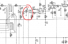
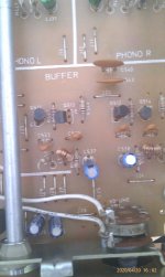
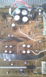
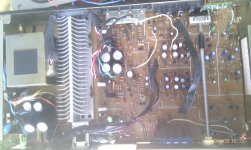
Some pictures to illustrate,
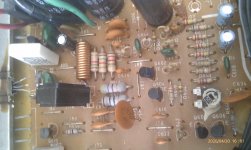
7 bipolars feeding the power outputs transistors. One discrete reg per channel. All pots are low cost carbons, treble pot is open at middle position but not the bass one if I understood. There are also a Bass EQ push button for + 3db 70 hz bump and also a loudness one for 100 hz & 10 khz bump.
It's a pretty decent sounding Proton AM200, the pcb is exactly the same as the 520 but with less options (no pre out, no headphones) for the 200 ! Phono section is simple but pretty good for the price of this low cost device, a poor's man Nad 3020 in the 80s...
Outputs bipolars are used by some Accuphase as well: Sanken SC2837 & A1186 : one pair by channel for 20 W !
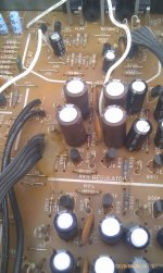
notice the two blue 1 uF Alcuson (aluminium copper .... ?) blue cap, a brand I never heard about. seems to be in +- - + serie at the bginning of the amp section, don't know if bipolars should be better or if polarized are andatory because the bipolars after... to my limited knowledged looks like signal serie dc blocking caps, but don't know at the end of the day !
7 bipolars feeding the power outputs transistors. One discrete reg per channel. All pots are low cost carbons, treble pot is open at middle position but not the bass one if I understood. There are also a Bass EQ push button for + 3db 70 hz bump and also a loudness one for 100 hz & 10 khz bump.
It's a pretty decent sounding Proton AM200, the pcb is exactly the same as the 520 but with less options (no pre out, no headphones) for the 200 ! Phono section is simple but pretty good for the price of this low cost device, a poor's man Nad 3020 in the 80s...
Outputs bipolars are used by some Accuphase as well: Sanken SC2837 & A1186 : one pair by channel for 20 W !
notice the two blue 1 uF Alcuson (aluminium copper .... ?) blue cap, a brand I never heard about. seems to be in +- - + serie at the bginning of the amp section, don't know if bipolars should be better or if polarized are andatory because the bipolars after... to my limited knowledged looks like signal serie dc blocking caps, but don't know at the end of the day !
Attachments

Last edited:
the symetric powersupply at the left near the traffo that feeds the 2 discrete regulators bench are only 350 uF/50v, for the debugging I sapped them with that I had on hands : 470uf/100v fresh caps. will be replaced with the good size after the fixing of course cause lead spacing is only 5 mm and the fresh ones are 7.5 mm spacing and too much huge width.
Attachments
Mooly,
should I source a 50k carbon pot with also the two outputs above the can (not aware if still produced), or do you think the alps pot was enough for debugging and I should find elswhere this floating ground on the pcb as you sugested ? Can this floating ground on the culppritt channel could come from the resistor biass pot which has a ground leg or a burned little bipolar transistor having a leg to ground ?
should I source a 50k carbon pot with also the two outputs above the can (not aware if still produced), or do you think the alps pot was enough for debugging and I should find elswhere this floating ground on the pcb as you sugested ? Can this floating ground on the culppritt channel could come from the resistor biass pot which has a ground leg or a burned little bipolar transistor having a leg to ground ?
Thank you Mooly for chiming in,
I tried to putt a stereo pot alps instead, no difference. But the original pot 6 leads feet has also two wires on the top of the can going towards elswhere on the circuitry.... I don't know, maybe mono push button ?
Could it be one bipolar of the buffer ? or one of the other tonal pot (I don't see EQ bypass on this integrated amp) or maybe a diode somewhere ? The balance pot seems to work fine. And I soldred again all the things if there was a cold joint.
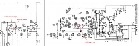
The extra wires on the pot are for the loudness circuitry and I suspect you would find it difficult to find a replacement anywhere. That said if you turn the pot to minimum then the wiper should be grounded and all signal removed... it has to be because you are shorting it to ground.
So you need to find out why that isn't happening. You should really trace the signal with a scope because that will show what is there or not.
If you short these points (pick the correct channel of course) the signal should disappear and it should go silent. If it does not then you need to find out why.
One lead of the pot (per gang of the pot) will go to ground so that is the ground point you should use.
Attachments
This volume pot with the extra pin is for the loudness control function, if you cannot buy a new volume pot with a loudness control pin, then you can use a normal 50K volume pot to replace it and just leave the loudness pin wire disconnected, the volume control function will be normal and just no more loudness control function which has no big problem in using the amp.
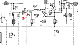
About the swings between -300 + 300 mV at the output, it is possible the softclip control circuit problem, please remove the softclip control cap at C643 location from the problem channel power amp to check if the output swings will be disappeared.
About the swings between -300 + 300 mV at the output, it is possible the softclip control circuit problem, please remove the softclip control cap at C643 location from the problem channel power amp to check if the output swings will be disappeared.
Attachments
Thank you Mooly, thank you Patrick,
The wires being about loudness purpose, so it's not the volume pot as I tried already with an moden alps already.
Have to dig according your advices. Have no scope at home and well I'm not purchase any things since the lock down but food, so it may last a little till I try to fix the thing.... I'm going to try wirh what I have on hands for the moments as i should have mosy of the TO 99 bipolar to try swaps and few common diodes too.
I'm reassured that te main Sanken are not broken, I will beginn with the ground scenario and first the pot resistor as seen in a hold thread from Massimo member here about the same Proton AM-200 refurbishing.
If any idea more let me know please,
Many thanks again for all your advices 🙂
Hello,
Some news, according & thanks the advices about a leak towards the Gnd by Mooly and Diymax62 old thread about this amp and trimpots, I finally focussed my search of a faulty part on few areas... having not a scope.
the culpritt part of the faulty channel was the resistor trimpot of the off set setup : short cut between the outputt of the trimpot and the gnd.
Thank you all for all the good advices, a friend is going to be happy to see back is beloved little amp 🙂
I have still few question, more curiosity oriented, please :
I see many of the lytics between interstages and transistors drivers are polarized and are 30 years old despite measuring capacitance being still good : should I swap them for brandnew bipolar as the cheap green Nichicon Muse for instance or is the polar choice is due also for decoupling voltage purpose as well, forbiden a bipolar choice ? Same near the volume pot caps are polarized and seems to be DC breaker purpose & filter with a resistor!
I also see many ceramic discs (pictures above) in the interstages in the pico farad range : should I swap them by little wima MKP for instance. Did they choose orange ceramic disc because of the price, cause I also see some green MKT, so maybe it's a design choice ? I have read ceramic class I do age as lytics but slower ???
Is there a simple way to increase the Sanken output wattage that are limited to 20W but can dissipate 100W from the datasheet : changing a BC transistor with a greater hfe : BC546a for a BC546c for instance.
Sorry for those more naive questions, anyway precision is not mandatory I assume cause the 50k volume pot is a cheap carbon with loudness feets.
Many thanks again for all the good advices.
Nothing you change will alter the power output. That is limited by the power supply voltage and current it can deliver.
Changing the gain of transistors would also not alter anything. This is because all circuits are designed to work over a huge range of variation in transistor parameters... that is the beauty of negative feedback... it makes all those differences disappear.
Very old electrolytics may be worth replacing, although the value may be correct the internal impedance might have increased as they age and dry out.
Power supply decoupling should always be using standard polarised caps as will be fitted now.
The signal caps... well I would always go with similar fitment to what is already there. Just buy recognised top brand parts like Panasonic etc.
Personally I would leave the ceramic caps alone. Price is always a factor but there is nothing wrong with what is fitted.
Thank you so much Mooly, I will proceed that way so 🙂
cool little amp , full discrete, the bipolars Sanken sounds fine and are used in the little diy module L12-2 and soe big Accuphase 🙂 . It has no the Power boost reserve (Power envelopp) that Nads have but is full symetric from the rectifiers to the outputt. So the carbon pot is still ok but not the trimpot for the offset of the faulty channel.
@BM : just a capacimeter and a DLM to set up the offset.
Last edited:
nad proton cambridge jungson covid.
Just a few that should be assigned to the depths of the Mariana trench or launched into the sun.
Just a few that should be assigned to the depths of the Mariana trench or launched into the sun.
Have a nad that has more 25 years, ok, just a pot and caps changed, the friend's low cost Proton from the early 90s breaked due to the trimpot. Cambridge, dunno. Nice dac in the 90s...
What are amp brands you never see in the workshop?
Modern good developped smps PS are said to lasr 30 years as some walldarts...any thoughs ?
What are amp brands you never see in the workshop?
Modern good developped smps PS are said to lasr 30 years as some walldarts...any thoughs ?
- Home
- Amplifiers
- Solid State
- Help me please debugging this amp fault.