I've got some ported boxes built and I think a) they're larger than optimal size, b) I'm very interested in transmission lines, c) the BR box is rather boomy sounding in the bass, and d) the box needs some bracing panels anyways.
I really like the idea of turning these into a folded MLTL system by adding some interior panels.
The T/S parameters are below, the box interior dimensions are (in inches) 13.75 deep, 22.5 tall, varying width depending on cross-sectional moment 12.5 to 10.25 with an average around 11.5 (at the driver mounted position it's 10.25 wide).
Driver is mounted at the centre of the front baffle.
Ports add up to 9"x1" cross sectional with a 14" length and the entrance to the ports are at the rear of the box (on either side - both are 9"tallx0.5"wide) dead centre vertically.
I've been trying to model this in Hornresp, but I think it's just not quite up to a MLTL design. Or maybe I'm not getting something. I also run linux so I can't get Martin King's worksheets running. Can anyone help me mock up a folded MLTL for these restrictions?
Code:
Zmin 3.95 ohm
fmin 180 Hz
f3 518 Hz
Le(f3) 0.978 mH
Motional impedance parameters
RES 29.47 ohm
LCES 30.811 mH
CMES 575.4 uF
RAMS 29470.838 mohm
Blocked impedance parameters
RDC 3.30 ohm
dR 0.31 ohm
Re 3.61 ohm
Leb 81.7 uH
Le 1.544 mH
Rss 1640.6 ohm
Ke 0.1592 S-H
Thiele-Small parameters
fs 37.6 Hz
Qms 2.906
Qes 0.491
Qts 0.420
Fts 89.6
Mms 30.89 g
Cms 0.579 mm/N
Rms 2.513 kg/s
Vas 35.77 litres
Bl 7.327 Tm
Eta 0.38 %
Lp (1W/1m) 87.95 dB
Dd 16.30 cm
Sd 208.7 cm^2
Added mass 8.40 g
Secondary measurement: Apr 4 14:19:39
Air temperature 20.0 C
Air pressure 1013.25 mB
Air density 1.2041 kg/m^3
Speed of sound 343.2 m/sI've done a couple sketchups so that you can get a better idea of what I'm thinking.
Here's the first, just what the box is like now. You'll notice there's vents on either side, but I've left the one side clear so that the TL ideas can be seen clearer. In reality both vents extend to the rear of the box.
Here's idea #1: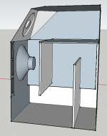
Idea #2: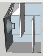
and Idea #3: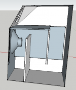
Assuming no taper is used, the TL's depth will be roughly 4.3"
Here's the first, just what the box is like now. You'll notice there's vents on either side, but I've left the one side clear so that the TL ideas can be seen clearer. In reality both vents extend to the rear of the box.

Here's idea #1:

Idea #2:

and Idea #3:

Assuming no taper is used, the TL's depth will be roughly 4.3"
AMLTL Design
Stochastic,
Based on the Accidental Mass Loaded Transmission Line (AMLTL) design http://www.diyaudio.com/forums/full-range/231951-accidental-mltl-technique.htmlfor the driver parameters you have above, here it the design I have:
40 liter volume (1.413 cu ft or 2442 cu inch), 37 Hz tuning
10 in wide baffle x 5.43 in deep x 45 in long with 3 inch dia vent x 7.4 in long.
Alternatively, a 10 in wide x 0.75 in tall x 6.34 in long shelf vent at the distal end.
Mount driver at 10 to 15 in from closed end, stuff 1 lb/cu ft in top 2/3rds of line (430 grams of polyfill).
So for a tri-fold MLTL, make a box 10 in wide x 15 in high x 5.43x3 or 16.3 in deep (all internal so need to account for thickness of material). For 0.5 in plywood, exterior dim is 17.8 in deep x 11 in wide x 16 in high box.
The closed end of the line starts at front bottom and goes up where driver is mounted, the goes down, then up again. The back top is where the vent goes. This is good because if near a wall, you can use wall loading to enhance bass.
See sketch. Alternate arrangement is to mount driver on 16 in wall at fold point and have vent facing front.
Attachments
Last edited:
Upon reading your first post more carefully I see you want to modify your existing box. I see why the bass was originally too boomy as the volume is well above optimal. Using my design, you can make it fit into existing box by throwing away some volume with internal panels to reduce volume. Just fold it to keep the cross sectional area the same at 54.3 square inches and length at 45 inches. So at 10.25 in wide the depth will be 5.30 inches. Not sure if this is enough depth for driver frame and magnet. Then make 2 folds along the 22.5 in length. So you see how much extra space you have. Kind of a bulky box with a lot of wasted space. I recommend building a new smaller box. It really is not that hard as all cuts are straight square cuts. If you really want to fully utilize volume of existing box as MLTL you need to change drivers to something with higher Qts and the volume required will grow.
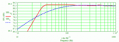
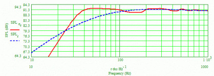
Using your average internal width to keep things simple and Martin's software, I modeled two ML-TLs, one a single-fold, 2-segment and the other a 2-fold, 3-segment. Both were tuned to 32-33 Hz (including the stuffing effects) and both had the first halves of their lines stuffed at 0.75 lb/ft3. The woofer was located exactly where it is now, meaning its center was 11.25" from the beginning of each line. Both used ports with a 3" diameter. The 2-segment line uses a single 3/4"-thick divider, making the line's depth be 6.5", whereas the 3-segment line uses two dividers that are 1/2" thick, making the line's depth be 4.25". The port in the 2-segment line has a length of 4.5" and its center is located 3.75" from the end of the line. The port in the 3-segment line has a length of 3" and its center is located 3.5" from the end of the line. I've attached the two modeled system bass response graphs showing the predicted results for an input to the woofer of 2.83 volts. I didn't see that you had listed the woofer's Xmax but assuming it's 6 mm Peak, you should be able to apply ~40 actual watts for either design before becoming concerned about over-driving the woofer, with the ports' air velocities not exceeding 4% of the speed of sound (just under 14 m/s) with the system simultaneously generating ~105 dB SPL above the knee in the response curve. The 2-segment model has the "prettier" response curve but the 3-segment model is more "TL-like" due to it having a longer line (68.5" versus 45.75" for the 2-segment). The 2-segment line has a slightly lower F3 but a sharper rolloff below the knee.
Paul
Paul
Attachments
So the drivers are some 8" woofers from an old pair of StudioLab brand Mini Tower Phase Inversion Monitors. I've fixed them up as they had rotting surrounds and metal dustcaps. I asked the forum here before as to help me identify them but got nowhere http://www.diyaudio.com/forums/multi-way/220779-can-anyone-idetify-these-8-midbass.html
Nice clean sounding speakers that I'm very glad that I've refurbished - almost cleaner than my Tannoy Precision 6p monitors.
The good news is that I've got another pair waiting for me to finish with this speaker build. I don't know the xmax on them as I measured the T/S parameters in REW after I fixed them up and that stat wasn't given.
I am encouraged by pkitt's graphs using the full box volume. But I am sort of wanting to keep the vents at the current 14" length and would be interested to see what a three-folded design might look like with a 9x1 inch vent 14 inches long.
Originally I did try stuffing the boxes with some books to take the volume down, but due to tuning issues and the midbass's hump in the bass anyways, I found stuffing them with polyfil to actually sound better (low tuning with a big volume creates a slow sloping extended shelf BR).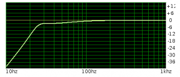
I have not yet put a crossover in - just currently running them from two channels of filtered digital content - so when I do, I could take a chunk of space out and dedicate it to a crossover cavity.
I really do have an itch to at least try turning this into a folded MLTL as the worst case results in me drilling holes in the internal dividers to return the cabinets to BR but with added bracing.
How do you determine the length of a fold anyways?
Would either of you mind running one of my folded designs through the simulation? I think option #3 is what I'm favouring.
I could take option #3 and extend the first vertical baffle (the one just behind the speaker) up to the horizontal baffle, then shorten the horizontal baffle to only span the two vertical baffles. After this I could cut the port back to be only ~6" in length. This would be the closest approximation to the suggested driver/vent placements I can think of. Thoughts?
Oh, and since the speaker has a depth of ~3.25" and the baffle is 1.5" thick, that only leaves 1.75" of the speaker magnet (1.75" radius, with 1.75" depth gives ~17 cubic inches volume) sticking into the throat of the TL.
Nice clean sounding speakers that I'm very glad that I've refurbished - almost cleaner than my Tannoy Precision 6p monitors.
The good news is that I've got another pair waiting for me to finish with this speaker build. I don't know the xmax on them as I measured the T/S parameters in REW after I fixed them up and that stat wasn't given.
I am encouraged by pkitt's graphs using the full box volume. But I am sort of wanting to keep the vents at the current 14" length and would be interested to see what a three-folded design might look like with a 9x1 inch vent 14 inches long.
Originally I did try stuffing the boxes with some books to take the volume down, but due to tuning issues and the midbass's hump in the bass anyways, I found stuffing them with polyfil to actually sound better (low tuning with a big volume creates a slow sloping extended shelf BR).

I have not yet put a crossover in - just currently running them from two channels of filtered digital content - so when I do, I could take a chunk of space out and dedicate it to a crossover cavity.
I really do have an itch to at least try turning this into a folded MLTL as the worst case results in me drilling holes in the internal dividers to return the cabinets to BR but with added bracing.
How do you determine the length of a fold anyways?
Would either of you mind running one of my folded designs through the simulation? I think option #3 is what I'm favouring.
I could take option #3 and extend the first vertical baffle (the one just behind the speaker) up to the horizontal baffle, then shorten the horizontal baffle to only span the two vertical baffles. After this I could cut the port back to be only ~6" in length. This would be the closest approximation to the suggested driver/vent placements I can think of. Thoughts?
Oh, and since the speaker has a depth of ~3.25" and the baffle is 1.5" thick, that only leaves 1.75" of the speaker magnet (1.75" radius, with 1.75" depth gives ~17 cubic inches volume) sticking into the throat of the TL.
Last edited:
The AMLTL technique I use is based purely on calculations as a bass relex which gices me the volume and vent dimensions for a tuning frequency, and by using a long aspect ratio enclosure, the transmission line effect is purely "accidental" hence the name Accidental MLTL or AMLTL technique - however, it seems to work quire well on at least 4 occasions so far. Thus, I cannot "model" a particular geometry other than to assume a line length and baffle width based purely on practical reasons, to derive the depth. The line length as I say is based on practical considerations but typically is 30 in for 3 in class drivers and 45 inches for 8 in class drivers (based on proven MLTL designs out there). 45 inches just happens to be 2x your 22.5 in dimension of your cabinet. If you want to model a particular geometry with variable CSA, the MJK sheets will be required.
Good luck with it.
Good luck with it.
AkAbak can do MLTL of course. I am waiting for Don Hills to make the original script which I can play with as I do not know enough about it.
For the sake of discussion and comparisons and to keep things simple, what I modeled assumed a rectangular box having internal dimensions of 11.5"W x 13.75"D x 22.5"H. As such, then, the divider in the single-fold, 2-segment box would be 16" long, and the two dividers in the 2-fold, 3-segment box would each be 18.25" long, in order to preserve each line's depth (6.5" and 4.25", respectively) throughout their entire lengths. For reference, the 3-segment line would appear pretty much like your proposed example #2.
To properly design a TL, whatever its configuration, you need to determine the overall tuning that results in the best overall response shape (whatever that shape may be for you) over its "flat" portion. Once you have that, how low the bass will go is only dependent on the volume in the line, with the provision that as you change the volume, you will also need to adjust the port's size appropriately in order to maintain that optimum system tuning frequency in an ML-TL.
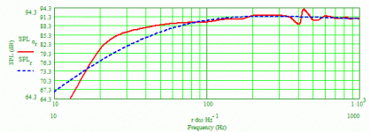
Noting what I said in the preceding paragraph, trying to use a port that's 14" long and has an area of 9in2 is simply not a good choice IMO. An equivalent circular port tube would have a diameter of 3.38". Ignoring completely how one would even fit into the 3-segment ML-TL a 14"-long tube, I did model how substituting that into what I modeled for the 3-segment line and have attached its system bass response for a 2.83-volt input. That tube shifts the system tuning down to ~23 Hz, way too low IMO for this woofer (YMMV, however), plus the response picks up a really ugly glitch around 400 Hz which probably cannot be mitigated to any extent.
Your existing box has some angles involved but those can be modeled and taken into account pretty accurately, albeit with a different modeling worksheet from Martin. Beyond just using your existing box, I think you need to place fewer restrictions/constraints on the design, like the 14"-long tube, if you hope to best utilize your box to obtain good to really good results. And, in case it's not clear, I'm not suggesting this be an "accidental ML-TL.
Paul
So the drivers are some 8" woofers from an old pair of StudioLab brand Mini Tower Phase Inversion Monitors. I've fixed them up as they had rotting surrounds and metal dustcaps. I asked the forum here before as to help me identify them but got nowhere http://www.diyaudio.com/forums/multi-way/220779-can-anyone-idetify-these-8-midbass.html
Nice clean sounding speakers that I'm very glad that I've refurbished - almost cleaner than my Tannoy Precision 6p monitors.
The good news is that I've got another pair waiting for me to finish with this speaker build. I don't know the xmax on them as I measured the T/S parameters in REW after I fixed them up and that stat wasn't given.
I am encouraged by pkitt's graphs using the full box volume. But I am sort of wanting to keep the vents at the current 14" length and would be interested to see what a three-folded design might look like with a 9x1 inch vent 14 inches long.
Originally I did try stuffing the boxes with some books to take the volume down, but due to tuning issues and the midbass's hump in the bass anyways, I found stuffing them with polyfil to actually sound better (low tuning with a big volume creates a slow sloping extended shelf BR). View attachment 344252
I have not yet put a crossover in - just currently running them from two channels of filtered digital content - so when I do, I could take a chunk of space out and dedicate it to a crossover cavity.
I really do have an itch to at least try turning this into a folded MLTL as the worst case results in me drilling holes in the internal dividers to return the cabinets to BR but with added bracing.
How do you determine the length of a fold anyways?
Would either of you mind running one of my folded designs through the simulation? I think option #3 is what I'm favouring.
I could take option #3 and extend the first vertical baffle (the one just behind the speaker) up to the horizontal baffle, then shorten the horizontal baffle to only span the two vertical baffles. After this I could cut the port back to be only ~6" in length. This would be the closest approximation to the suggested driver/vent placements I can think of. Thoughts?
Oh, and since the speaker has a depth of ~3.25" and the baffle is 1.5" thick, that only leaves 1.75" of the speaker magnet (1.75" radius, with 1.75" depth gives ~17 cubic inches volume) sticking into the throat of the TL.
Attachments
Last edited:
- Status
- Not open for further replies.
- Home
- Loudspeakers
- Multi-Way
- Help me model a folded MLTL?
