Can someone tell me which resistors in this diagram are responsible for setting the gain? This is a LPF using t072 opamps. It would be great to know exactly which caps and resistors are setting the lpf. I have been struggling to read opamp diagrams and translate them to what I'm looking at on the PCB itself.

R3 & R4 set the drive gain. R3 + R4 / R4 = gain.
R13 & R14 (or at least that's what they could be) set the low pass gain. The pots set the phase shift or null point that can be varied.
R13 & R14 (or at least that's what they could be) set the low pass gain. The pots set the phase shift or null point that can be varied.
Attachments
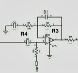
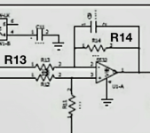
Well the first opamp is some sort of roofing filter I suspect, perhaps limiting to 20--20kHz. The second is a Sallen-Key low pass filter with the resistors tunable - Sallen Key filters have 0dB gain in the passband. Only the output fader seems to affect gain.

Thank you for the help. I poked around a bit last night and thought those were the ones but wanted to make sure I was understanding it right. I'm still learning so don't trust myself completely yet. I put the values in an online calculator and come up with 23hz-120hz cut off range. It sounds much better than 2 other cheap preamps I've tried from Amazon but still doesn't give that tight clean bass. I have a 7 band parametric EQ for car audio that only has a 60 or 120hz selectable LPF and it sounds much better. I've yet to figure out the differences between LPFs that make the bass sound so much better. Is it the opamps that make the most difference? I know it's probably a combination of layout, parts used, and opamps but is there one component that I can change that makes the most noticeable improvement?
Not the opamps, its the filter circuit components that determine the response. Parametric EQ probably has more Q than a 2-pole low-pass filter, which I'm assuming is Butterworth as that's the commonest.