Howdy everyone, I'm new here, and I need some advise on my first guitar amp build.
It's a 15w lightning type clone, based on my own interpretation of the original schematic and the various interpretations knocking around.
I'm struggling with the layout. I'm worried about the preamps being close to the output transformer and equally worried about the output being too close to the power. I've used the headphone trick to determine that the output needs to be as far away as possible from the power. (The chassis is quite small for the size of these transformers!) I know there's always going to be compromises but I'm struggling to determine which ones are best.
I've come up with 3 possible layouts. Can anyone comment on which is best or recommend an alternative?
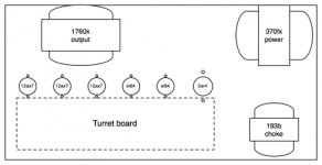
Layout 01 - facilitates the neatest wiring, but has noticeable 60hz hum
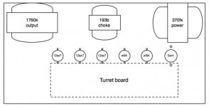
Layout 02 - gives a quiet output, but puts preamp 1 very close to the OT
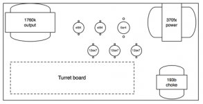
Layout 03 - also gives a quiet output and keeps the preamp tubes far away from the OT, but makes for tricky wiring
It's a 15w lightning type clone, based on my own interpretation of the original schematic and the various interpretations knocking around.
I'm struggling with the layout. I'm worried about the preamps being close to the output transformer and equally worried about the output being too close to the power. I've used the headphone trick to determine that the output needs to be as far away as possible from the power. (The chassis is quite small for the size of these transformers!) I know there's always going to be compromises but I'm struggling to determine which ones are best.
I've come up with 3 possible layouts. Can anyone comment on which is best or recommend an alternative?
Layout 01 - facilitates the neatest wiring, but has noticeable 60hz hum
Layout 02 - gives a quiet output, but puts preamp 1 very close to the OT
Layout 03 - also gives a quiet output and keeps the preamp tubes far away from the OT, but makes for tricky wiring
Attachments
How about layout 3, but put the turret board in the middle, preamp tubes at the front of the chassis, rectifier and output tubes at the back of the chassis?
Thanks doozerdave ... interesting idea - and not one I'd considered - what's your reasoning behind it?
You don't have to worry too much about the output tubes being too close to the power transformer. I expect the output section to be push-pull (AB1). Small interferences will cancel out.
I do find it's good practice to have the most sensitive parts (first stages) and power supply on opposite sides of the chassis.
Why are you concerned about the preamps tubes being to close to the output transformer? Oscillation can occur, but at these powerlevels...? Plus, the magnetic field is greatest parallel to the core.
Because of the above, option 1 is best IMO. Doozerdave's suggestion is a good one too.
Thanks funk1980, I think you're right: the preamp tubes will be shielded, so it probably is the lesser evil to have them right in front of the OT rather than near the PT.
#1 keeps the all associated input circuitry farthest from the PT even if shielded. Obviously, a larger chassis is best. Are you totally set on that size? Many people make the mistake of trying to squeeze too much in too small of a space. Stray capacitance also needs to be addressed, enough room to keep heater wires out of the way, etc. What are the dimensions of the chassis?
It gets your input and output stages far apart. Also coming off both sides of the turret board might help to ease the wiring.Thanks doozerdave ... interesting idea - and not one I'd considered - what's your reasoning behind it?
@boobtube: chassis isn't exactly small at 16x8x2" (these transformers are really [too] big). Next easily available chassis was 17x10 which I felt was too deep for a nice sized cabinet.
Does anyone have an opinion on Choke placement? "Below" the PT or between the PT and OT?
Does anyone have an opinion on Choke placement? "Below" the PT or between the PT and OT?
Yes, you're right IMHO, that's plenty good. That's the size I have for my upcoming,not yet totally planned project. I'll be watching and hoping to learn from this thread. Keep us posted on your progress! #1 still gets my vote.
I would think that generally the choke should be as close to the output of the 5AR4 as possible. You want to minimize the length of the pulsed DC lines to minimize switching noise radiation.
I would think that generally the choke should be as close to the output of the 5AR4 as possible. You want to minimize the length of the pulsed DC lines to minimize switching noise radiation.
Hi doozerdave, do you think that with only the required current draw of 2 EL84s plus a few mA for the preamp that it would be an issue? I've wondered about that as I'm also planning a project with the same size chassis.
Is there any info that you know of how far the magnetic field of specific currents at specific voltages emanate from the wires? Thanks
That's tricky question. I'm sure it's possible to calculate the field strength but once you get up to higher frequencies and lots of frequency content (don't think about audio or line frequencies, we're talking about diode switching frequencies) you start getting into transmission line territory. Screw the math... LOL Basic power supply design says keep everything as tight as possible until it's clean DC. With a tube rectifier it shouldn't be as noisy as a silicon rectifier but you still want to do a nice job. You should always be able to have your PT, rectifier, choke and bulk caps in a tight arrangement in one corner of the chassis. Once you have clean DC you can run it across the chassis (keeping well clear of AC heater wires of course) and have local bypass caps and PI filters at each stage.
Orientation of the choke is a concern too. Theory tells you to place the cores of nearby magnetics 90 degrees from each other to minimize induction, but this might be something to experiment with. I've seen chokes at odd angles in some amps.
Orientation of the choke is a concern too. Theory tells you to place the cores of nearby magnetics 90 degrees from each other to minimize induction, but this might be something to experiment with. I've seen chokes at odd angles in some amps.
This is all really helpful info. There's so many factors to consider with tube amps it's crazy.
I've thought about it a bit more and played around with the locations. OT and choke are dead quiet in this one, wiring should be pretty straight forward and the first 12ax7 is a reasonable distance from the OT.
What do you think of layout 4?
I've thought about it a bit more and played around with the locations. OT and choke are dead quiet in this one, wiring should be pretty straight forward and the first 12ax7 is a reasonable distance from the OT.
What do you think of layout 4?
Attachments
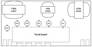
Looks good. I like that you moved V1 further from the other components. And it is closer to the input jacks. If it is dead quiet, why mess with it?
Last edited:
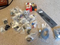
The last delivery just came!!! Everything I need is now sitting on my study floor... 100's of tiny bags of goodness. Now where do I start ...
Attachments
Last edited:
You start with the power supply 🙂 I don't see any plan for placement of large power supply capacitors. What's your plan for them?
My plan was to just have everything on the one turret board. But my test fitting last night revealed it's going to be very squashed on there. I'm particularly worried that the last power cap will be pretty much touching off the big power resistor.
Should I be worried?
Should I be worried?
Maybe. Electrolytic caps don't like too much heat. It can decrease their life span. That said, we've all played through 50 year old, all original amps that don't hum badly.
Remember there is an option of putting the last filter cap of the B+ rail supplying the first input tube(s) closer to those tubes. The caps don't all have to be next to each other, if this helps any.
My Hot Rod Deville has the last 22uF cap over by the first preamp tube. I would imagine this is for shorter wire runs from the cap to the plate load resistor because they are the most sensitive tube(S). Not exactly sure of the theory involved. But it is done.
Maybe if you have extra space, you could mount it on a pair of small lug strips off the main board.
Last edited:
lightreel, if you haven't already seen The Valve Wizard's site, this is a must read, Power Supply
Also click the Home button to find loads of information about tube amp design.
Also click the Home button to find loads of information about tube amp design.
- Status
- Not open for further replies.
- Home
- Live Sound
- Instruments and Amps
- Help me choose a layout