These were factory made, but now I hope to DIY repair. woofers (5000hz cross) sound fine) What is my 1st test? Do I test for hi-voltage @ tweeter panels? If so, where do I put my VOM leads. The tweeters appear to be parallel wired. they are single ended.What volt...500-1500? Thanks from an old man newbie.


Last edited by a moderator:
You must have high v multimeter.?..you can kill your meter...
Most Diy guys only have 600- 1kv meters .....if there lucky...........ck it frist
you bias be over 1k...
I would think if things are right.....so the tweeters have no output??
after that I will let other chim in....I never seen these speakers
Most Diy guys only have 600- 1kv meters .....if there lucky...........ck it frist
you bias be over 1k...
I would think if things are right.....so the tweeters have no output??
after that I will let other chim in....I never seen these speakers
Last edited:
I'm seeing just two wires feeding those tweeters... a black common lead and a red lead going to the diaphragms(?). I'm thinking they must driven one-sided by a single stator.
There is a single red lead going from panel to panel. The blk. ground wire goes to (1) panel, then they are grounded to one another by a tab or leg. Do I check the hi-volt at each red lead and ground leg? If the volt. is there, I will remove ,disassemble and inspect the dia. If volt. is insufficient, i will back up. When i removed the back panel, it was immediately apparent they are all original. I hope that is a positive! These were marketed by Radio Shack for about 10 yrs. Word is, they sold a bunch. they are at least 45 yrs. old. Info is scarce, to say the least. Thank you all!
Hopefully someone more knowledgeable than I will chime in soon and help you troubleshoot those tweeters.
If they were conventional push/pull stats I'd first verify the panel (red lead) is receiving a DC bias voltage but then, I'm not sure whether you have a single stator swinging AC and reacting against a DC charge on the diaphragm or the diaphragm/stator are both swinging AC and reacting against each other. Since you have an AC power cord, I'm thinking the red lead is feeding DC to the diaphragms-- but I don't know that for sure.
No harm in plugging in the power cord and checking for DC voltage on the red lead-- if you have a high voltage probe or a high voltage capable meter.
Measure voltage at the red and black wires. It should be in the 200Vdc to 350Vdc range.There is a single red lead going from panel to panel. The blk. ground wire goes to (1) panel, then they are grounded to one another by a tab or leg. Do I check the hi-volt at each red lead and ground leg?
So, no problem measuring with most DVMs(Digital Volt Meter) which have 10Mohm input impedance and are usually fine for 500 - 600V.
If DC voltage is low, it is most likely the rectifiers or caps.
To help troubleshoot, it would be very helpful if you could take a picture of the backside of the PC board so the circuit connections to the parts can be identified. Then it will be easier to point out what to measure where to identify failed parts.
Thanks, bolserst. DOD...dumb question of the day; Do I have to plug in these speakers,turn them on, then wait for a few days?
Real. Elect. 2a underside P.C. board.
 I hope this is visible. I hope it helps you help me! Much obliged
I hope this is visible. I hope it helps you help me! Much obligedNo. After plugging them in you should have full output within a minute.Do I have to plug in these speakers,turn them on, then wait for a few days?
The pic of the bottom of the PC board is perfect!
But, the left hand side copper layout is making it difficult to identify parts connection based on just the top view pic in your first post.
Could you post an image of the top of the PC board with similar image quality to the bottom view you just posted? That should allow me to figure out the circuit more easily.
Dear Mr.bolserst, I will do my best. Every pic is from some 'net site. I have yet to remove the stapled O.E. matting covering everything. It looks completely orig. I just got a meter on loan; am going inside today. Thanks again.

Hey...I found that pic online too! 😉pc board top view. Clearer?
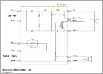
It was good enough to trace out the high voltage and transformer drive signal for the electrostatic panels. Still need a better top view of the crossover part of the board, to draw up that part of the circuit. But, it may not be needed to get them working.
Do you have a DVM?
If so, I'll post some measurement steps to isolate faulty parts.
BTW, have you looked at the back of your PC boards?
Are the copper traces green and corroded around some of the solder joints like the pic from the internet you posted?
If so, the first step would be to clean up the corrosion and re-solder the affected component wires.
During lunch, located some additional pics showing a later version of the PCboard on ebay.Do you have a DVM?
If so, I'll post some measurement steps to isolate faulty parts.
It did make it easier to reverse-engineer the circuit. I was surprised to find it used a series crossover network. If I understand the circuit and catalog page correctly, using the black and green wires for audio input would give a response that matches the previous version (model 2, not 2a) of the speaker. How's THAT for backwards compatibility! Using the black and red wires for audio input applies a shelving network for baffle compensation providing more extended bass response, although lower overall sensitivity.
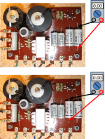
First thing to check is the voltage across each half of the voltage doubler.
Each should read 150 - 170 Vdc.
Let us know what you find out and we'll go from there.
Attachments
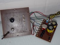
Elec. 2a, in the belly of the beast.
I immediately noticed different colored staples holding matting covering P.C. board. I knew someone had been there. The red & blk leads leaving the board going to the dia. show 314v. The same leads @ the dia. solder joints show same 314v....also, 1 staple missing from the piece of matting @ dia. lead area. I heard (did not see) a small sound of arcing when I 1st probed the pos. dia. on input tweeter.This pc board is slightly diff from 'net pix..may not be important right now. Tweeter I.D. is: TWEETER, SC1a, made in Japan. I have not checked any other voltages. Do I need to? Thanks,civil6!
I immediately noticed different colored staples holding matting covering P.C. board. I knew someone had been there. The red & blk leads leaving the board going to the dia. show 314v. The same leads @ the dia. solder joints show same 314v....also, 1 staple missing from the piece of matting @ dia. lead area. I heard (did not see) a small sound of arcing when I 1st probed the pos. dia. on input tweeter.This pc board is slightly diff from 'net pix..may not be important right now. Tweeter I.D. is: TWEETER, SC1a, made in Japan. I have not checked any other voltages. Do I need to? Thanks,civil6!
That is good news! 314V at the red & black wires show your HV bias supply is working fine and that none of the ESL assemblies have internal shorts. No other voltages to measure for now. It is possible that the connections to the conductive coating on the diaphragm are bad, but for know we will assume they are ok.The red & blk leads leaving the board going to the dia. show 314v. The same leads @ the dia. solder joints show same 314v.... I have not checked any other voltages. Do I need to? Thanks,civil6!
The next steps would be…
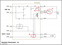
1) Check tweeter volume control: does turning the volume knob vary the output of the ESL tweeters? As a check, you can bypass the control by shorting terminals #5 & #6 at the PC board. This would put the tweeter level at maximum.
2) Check the 5uF capacitor that is in parallel with the woofer. Since this is a series crossover, if it is not bypassing the highs around the woofer, the ESL tweeter won’t have much output. If you have a capacitor in the 3uF – 10uF range, connect between the black and yellow wires going to the woofer from terminals #8 and #9. If the output jumps up in level, you know the 5uF crossover cap is bad and needs to be replaced.
3) Check the 0.047uF capacitor that is in series with the transformer secondary (between terminals #3 and #5 on the schematic). To test, connect a new capacitor (0.047uF to 0.1uf) between terminals #3 and #5. If the output jumps up in level, you know the 0.047uF isolation cap is bad and needs replaced.
Forgot to ask...how are you connecting audio to the speaker? For now, I would recommend connection between the black and green wires.
Attachments
Last edited:
All three tests (l-pad,5uf,.047uf) neg., no change. I carried to my neighbor, he will verify my work. The other spkr specs @ 322v @ same 2 locations. I will do same 3 tests on that unit this weekend. I see nichicon caps inside. Are those 4 blk. vertical caps tantalums? If I have to (and able to) repair the dia., is there any prospect of longevity? Do you see any feasibility/longevity issues with active crossover use? The spkrs. are completely disconnected now. Thanks, civil6.
Real Elec 2a...10 Oct.
I delivered a spkr to Mark Stanley. He is a well respected elect tech. in my area. I can't go beyond what I have done so far. My inability to resolve this issue is a wild card. The dia. panels will most likely have to be separated. I don't feel remiss about my own DIY capabilities. My expectations are still high! I own some some wonderful Altec Lansing VOT's and and AR's, and full range Fostex spkrs. This is the first time I have attempted to see what it's like on the inside. Those of you replying have my utmost respect. Respectfully, civil6.
I delivered a spkr to Mark Stanley. He is a well respected elect tech. in my area. I can't go beyond what I have done so far. My inability to resolve this issue is a wild card. The dia. panels will most likely have to be separated. I don't feel remiss about my own DIY capabilities. My expectations are still high! I own some some wonderful Altec Lansing VOT's and and AR's, and full range Fostex spkrs. This is the first time I have attempted to see what it's like on the inside. Those of you replying have my utmost respect. Respectfully, civil6.
I have been using a 1.8 watt solid state amp. Should I consider a higher, more controlled constant current amp? Ya!
You didn’t mention, did the output level of the ESL tweeters change when you rotated the control?All three tests (l-pad,5uf,.047uf) neg., no change.
Did you check the back side of the PC boards for corroded solder joints?
An LCR meter would allow you to measure the capacitance, but I don’t think it is necessary for this repair.
Based on your testing to date, the most likely problem is what we had hoped it wasn't...connection to the diaphragm coating.
Can you tell if all 4 of the ESLs have the same output? Or is one or two slightly louder? You don’t need a lot of power to test if the tweeters are playing at the correct level relative to the woofer, but 1.8W won’t be able to play music on them to their full capability.
I have not personally repaired/replaced the diaphragm on this particular model, although I have on some similar Philco tweeters. I’m curious enough about the construction technique used, if you would like to mail me one I could determine repair method and send it back to you in working condition with instructions for you to use to repair the rest. If interested, send me a PM.
- Status
- Not open for further replies.
- Home
- Loudspeakers
- Planars & Exotics
- HELP! Low tweeter output, hybrid esl