Hello all,
Just want to preface this post by saying i have very little experience
building or repairing any tube gear, so i’m reaching out to the experts for help.
My objective here is to lower the capacitance load my MM phono cartridge sees. It's a ClearAudio Maestro and according to its specs, it likes 100pF.
As things are right now, the 1.2 meter cable and the tone arm wiring are 200pF.
Additionally my preamp’s (MFA Magus) phono section has 47K shunted by 200pF according to the manual.
So total it’s 400uF not including any Miller Capacitance. I can swap out or shorten the cable as i don’t need 1.2 meters and knock off 100pF.
My issue is the caps in the phono section. I’d like to remove them or replace them with a lower value. Only trouble is i can seem to locate them, either by looking at the board or the schematic. The closest i’ve seen is a pair of .22k caps (C3 & C 11). I’m attaching the schematic hoping someone can take a look and advise. I’d appreciate any guidance. Thanks
Attachments

So let's start-up again in a different section, but still not show the actual equipment, or link to a picture.trouble is i can seem to locate them
Is anything connected to the "loading" connectors?
You could remove the grid-anode and grid-cathode capacitors of the first stage, but they are probably there for a reason, for stability or for RF immunization maybe.
You could remove the grid-anode and grid-cathode capacitors of the first stage, but they are probably there for a reason, for stability or for RF immunization maybe.

I’ll post a picture of the unit tomorrowSo let's start-up again in a different section, but still not show the actual equipment, or link to a picture.View attachment 1069537
View attachment 1069538
The loading jacks were empty.Is anything connected to the "loading" connectors?
You could remove the grid-anode and grid-cathode capacitors of the first stage, but they are probably there for a reason, for stability or for RF immunization maybe.
I have a pair of 150K resistors there to load it down to 36k.
Yes. Manual states ‘input capacitance 47K shunted by 200uF’. I see the pair of 47K resistors, but not the caps.Is the specified 200 pF input capacitance also specified with the loading connectors open?
I’ll post a picture of the unit tomorrow. The four orange disc shaped components each read AE 10K 1KV
Attachments
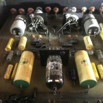
So 10 pF +/- 10 % with 1 kV maximum working voltage. That matches the schematic.
If the first stage were working open loop, Miller effect could multiply the capacitance of the capacitor between grid and anode to many hundreds of picofarads equivalent at the input.
If the first stage were inside a feedback loop with huge loop gain, there would be no Miller effect and that 10 pF capacitor would just add 10 pF to the input capacitance.
In reality, the first stage is inside a feedback loop with limited loop gain. It is not straightforward to calculate how much the 10 pF capacitor between grid and anode contributes to your 200 pF, but it could be a substantial part.
So as PRR has been hinting at since post #2, disconnecting them and checking if the amplifier remains stable would be a logical step.
The grid-cathode cap is not Millered but bootstrapped. It has no audio effect. Leave it alone. Or raise it to 100pFd (acts-like 5pFd, but may swamp radio).
I think I'll leave everything as is for now. Was hoping it would be an easy fix to just remove / replace a pair of caps once I knew where they are. But from what if read so far it's too out of my level of expertise. I can cut the the tonearm cable down and knock off about 100pF. That and loading down the resistance should help.So 10 pF +/- 10 % with 1 kV maximum working voltage. That matches the schematic.
If the first stage were working open loop, Miller effect could multiply the capacitance of the capacitor between grid and anode to many hundreds of picofarads equivalent at the input.
If the first stage were inside a feedback loop with huge loop gain, there would be no Miller effect and that 10 pF capacitor would just add 10 pF to the input capacitance.
In reality, the first stage is inside a feedback loop with limited loop gain. It is not straightforward to calculate how much the 10 pF capacitor between grid and anode contributes to your 200 pF, but it could be a substantial part.
So as PRR has been hinting at since post #2, disconnecting them and checking if the amplifier remains stable would be a logical step.
Thanks to all for taking the time to reply. Much appreciated.
One other thing I forgot to mention in my last post. While having the unit open and looking for the caps, I noticed how dirty the PCB board was. There is also some minor rust here and there on a few of the through holes as well as flux on some solder joints. Whats the best way to clean things up and which products to use. Thanks
- Home
- Source & Line
- Analogue Source
- Help Locating Imput Caps For MFA Magus Phono Stage