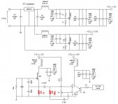
I have constructed this clock, as attached, for my CD player. It is based on Kwak Clock, without the power supply as I only have a single ended power supply in my CDP.
Initailly, the circuit is based on KC6. Both the Jfet and AD8561 shared the same power supply of +5V (+V1). I have noticed that with +5V supply the output of AD8561 (clock signal) peaks at about 3.8V. I decided to try out if a clock signal of higher amplitude would make a difference. So I added in the additional circuit to give +V2 of 5.9V specially for the chip AD8561.
In my orginal construction, R2 is a metal film resistor. I decided to changed it carbon film. The rest of the resistors are all carbon film. R1 remains at 270ohm.
After done all these, I cannot detect a oscillation from the circuit, using a osilloscope. The voltage at Drain of the Jfet is 4.9V. Voltage at pin 1 of AD8561 measured to be 5.9V as well. I have tried to isolate the Jfet oscillator circuit from the AD8561 circuit + powersupply. Resistor R1 was also changed to 1kohm.
I have changed 3 pieces of J309, and still have not idea what went wrong. The circuit was orginally working.
I wonder would there be a possibility that the Crystal oscillator actually failed.
Please advice.
Thanks
SW
Attachments
alfsch said:Hi,
test: voltage on source/r1 ?
+ tested another crystal?
alf
Tested around the parts of the oscillator circuit, could not pick up any signal, only +5V or 0V.
I only have one piece of 5ppm crystal, will try the one pulled out from my CDP.
Regards,
SW
Lars Clausen said:I would exchange the 39p and 68p in the oscillator to some additional gain.
are those values critical?
I can't find 39p and 68p here 🙁 Also no NPO
Hi,
at source/r1 you must get some voltage, 2V or so, otherwise this shows, the fet draws no current --> no osz... check fet connections, or try a new one, prob you killed it.
alf
at source/r1 you must get some voltage, 2V or so, otherwise this shows, the fet draws no current --> no osz... check fet connections, or try a new one, prob you killed it.
alf
Yes in the oscillator they actually form a sort of transformer, with the lower capacitor's charge as 'primary' and the higher (geographically on the sch) capacitor's charge as 'secondary'.
Please note that since the input charge equals the output charge, the transformed voltage is higher with lower capacitance.
The inductances and capacitances of the xtal are also used to close the transformer loop.
Yes those values are (very) critical for operation.
Please note that since the input charge equals the output charge, the transformed voltage is higher with lower capacitance.
The inductances and capacitances of the xtal are also used to close the transformer loop.
Yes those values are (very) critical for operation.
OK, so values are critical.
Elso said that ceramic NPO are the caps to use.
Is THIS also critical?
I can find NPOs here, but with lower values. And The required values, but not in NPO...
Elso said that ceramic NPO are the caps to use.
Is THIS also critical?
I can find NPOs here, but with lower values. And The required values, but not in NPO...
NPO's have a good low temperature coecifient, and are good for this application. Other ceramic caps may also work, but give a poorer temperature stability. Not nessescarily a problem.
You can also get better types: MICA caps are even better than NPO's, if you can get them.
C0G's are also good, same as NPO's or slightly better.
You can also get better types: MICA caps are even better than NPO's, if you can get them.
C0G's are also good, same as NPO's or slightly better.
Is NPO meaning something like "low temp coef" ?
I agree that the tempco won't be a big issue here, I think the temp won't vary that much inside the player.
By mica, are you meaning silver mica?
And is C0G ceramic too?
I agree that the tempco won't be a big issue here, I think the temp won't vary that much inside the player.
By mica, are you meaning silver mica?
And is C0G ceramic too?
I can have micas, but a pack of 5 for 15€, so 30€ for only 2 caps I'll use
I'll stay with the ceramic 😀
BTW, thanks for the advices
I'll stay with the ceramic 😀
BTW, thanks for the advices
Just one problem.......
He never mentioned what frequency it operates at. Kinda hard to give the right advice without knowing that.
But what do I know?
Jocko
He never mentioned what frequency it operates at. Kinda hard to give the right advice without knowing that.
But what do I know?
Jocko
Jocko: Doesn't really matter, as long as the xtal has a defined serial capacitance (typically 15 - 30 pF) the frequency of the xtal does not influence the values these two capacitors should have.
And if they are 68 and 39 pF defined by ELSO KWAK i will trust this to be the right values for his version of a Collpitts oscillator.
Have a nice day .. 🙂
And if they are 68 and 39 pF defined by ELSO KWAK i will trust this to be the right values for his version of a Collpitts oscillator.
Have a nice day .. 🙂
Yes, it does matter.
The ratio remains fixed, but the values change as a function of frequency.
Also, it is not spec'ed as whether or not resonance is measured with a series or parallel load. Probably parallel, since most CDPs are that scheme.
But if it is 16 MHz......the load is most likely 20 pF, not 32 pF.
Jocko
The ratio remains fixed, but the values change as a function of frequency.
Also, it is not spec'ed as whether or not resonance is measured with a series or parallel load. Probably parallel, since most CDPs are that scheme.
But if it is 16 MHz......the load is most likely 20 pF, not 32 pF.
Jocko
Re: Just one problem.......
The frequency is 16.9344 Mhz.
If I can remember is the series capactance of the crystal is 30pF. Both 68 and 39 pF cap are silver mica.
The 0.01uF cap between R1 & R2 is a SMD ceramic cap.
Jocko Homo said:He never mentioned what frequency it operates at. Kinda hard to give the right advice without knowing that.
But what do I know?
Jocko
The frequency is 16.9344 Mhz.
Lars Clausen said:Jocko: Doesn't really matter, as long as the xtal has a defined serial capacitance (typically 15 - 30 pF) the frequency of the xtal does not influence the values these two capacitors should have.
And if they are 68 and 39 pF defined by ELSO KWAK i will trust this to be the right values for his version of a Collpitts oscillator.
Have a nice day .. 🙂
If I can remember is the series capactance of the crystal is 30pF. Both 68 and 39 pF cap are silver mica.
The 0.01uF cap between R1 & R2 is a SMD ceramic cap.
The capacitance value is related to the xtal's manufacturing specifications, not the frequency of the oscillator.
Overmind:
Looking at your schematic, it seems there are no resistors to drop the voltage from the 8V ragulator to the 5 and 5.9 V shunts. Are you relying on the series resistance of the chokes?
Did you check the voltages over the shunts, to make sure none of them are burnt?
Good luck ... 🙂
Looking at your schematic, it seems there are no resistors to drop the voltage from the 8V ragulator to the 5 and 5.9 V shunts. Are you relying on the series resistance of the chokes?
Did you check the voltages over the shunts, to make sure none of them are burnt?
Good luck ... 🙂
Lars Clausen said:The capacitance value is related to the xtal's manufacturing specifications, not the frequency of the oscillator.
I was informed Cs of the crystal is 30pF.
Lars Clausen said:Overmind:
Looking at your schematic, it seems there are no resistors to drop the voltage from the 8V ragulator to the 5 and 5.9 V shunts. Are you relying on the series resistance of the chokes?
Did you check the voltages over the shunts, to make sure none of them are burnt?
Good luck ... 🙂
I am using the DCR of the inductor to drop the voltage from 8 to 5 and 5.9V. I did not measure the voltage across the inductor. However I am able to measure 5 and 5.9V at the cathode of the LM431s. I think this is ok.
The KC was working till I added in the 5.9V regulator for the AD8561 and change a few resistors.
Thanks
SW
- Status
- Not open for further replies.
- Home
- Source & Line
- Digital Source
- Help! Kwak Clock - Partial adoption