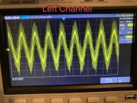
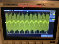
Hi all — trying to improve my very limited technical understanding. With my F6 amplifier, I have a very faint hum in both channels, but more pronounced in the left. I previously had an F5 in the same chassis, with the exact same observations. I finally measured both channels with a scope and got the attached two results — a fairly clear peak to peak sine wave of about 4mv in the left channel, and a bit of a hash in the right. These measurements were taken with the F6 inputs shorted and with no load. Connecting the input rcas made no difference in the readings. My best guess is that this is induced mechanical hum from the transformer — not a ground loop — but does anyone have the time or patience to explain to me how to interpret these measurements (or, even better, capture more meaningful ones)?
Overall, there’s nothing wrong with the amp. It sounds wonderful, I’m just interested in learning more.
Thanks!
Overall, there’s nothing wrong with the amp. It sounds wonderful, I’m just interested in learning more.
Thanks!
Attachments
Post some clear photos of the boards and chassis here, and some may be able to help you.
Looks like low level HF oscillation. It may be possible to clean it up with some wiring changes.
Looks like low level HF oscillation. It may be possible to clean it up with some wiring changes.
Last edited:
The left plot shows some 60Hz sine with some rf smear on it.
To see more, do a 2 channel plot with both outputs displayed simultaneously. Trigger source should be left channel.
And you should learn to setup your scope manually instead of autosetup.
A scope is a basic tool for analysing electronic circuitry. Looking for low level noise the limitations are obvious: You can hear output noise with levels below 1mV - but these disappear in the noise floor of the scope or some rf-noise induced from nearby power supplies or both. All in all a modern scope with a bandwidth in the ballpark of 100MHz is not suitable to measure low level audio signals. This is the domain of a PC with a soundcard and some analyzing software like ARTA.
Last edited:
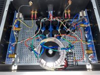
The speaker output terminals are pretty close to the input transformers, so there may be some
HF coupling happening there. Especially move the yellow output wire away from the input transformer.
Move the blue rectifier wires farther from the input transformer. Move the input cable up and away
from the power supply, more like the other channel. If you keep the amp as it is now, you may want
to add mu metal shields over the input transformers.
Last edited: