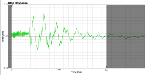
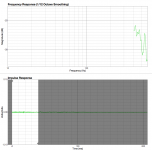
I'm trying to time align the drivers my three way horn system, but I don't know much about this side of things and am having difficulties interpreting the measurements. I'm using FuzzMeasure and decided to measure my mid bass horn and high frequency horn with a short 1000ms sweep around the crossover frequency (510Hz). The sweep runs between 400 and 600Hz. I've shown the impulse step graph below but am not sure how to interpret it.
Is it as simple as the small waves are the high frequency horn (Altec 288-8K in Yuichi 290 horn) and the large waves are the mid bass horn (EVM 15L in 70Hz front horn), in which case the delay looks to be about 17ms. This translates to over 6 metres in physical path difference. There would be no more than a few inches in physical difference between the two acoustical centres … or is one wired out of phase potentially?
Can someone offer some guidance here?
Attachments
Can you post the impulse response? The step response I believe will be showing you the decay, though I am a bit surprised by the amount of time it is taking to get back to rest. Was this taken in room? Perhaps you are seeing the echo's as they diminish in value.
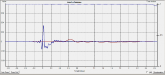
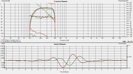
With the impulse response the highest peak is actually the high frequencies, the low frequencies are a much lower peak.
Attached are measurements I made of my MTM (blue) and 10" woofer red curve (with time zero locked). As you can see there is about 0.6ms time difference, probably about 23cm.
edit: zooming in on the individual impulses allows me to see the time difference more accurately.
Tony.
Attachments
Last edited:
Thanks Tony,
I'm still finding my way around FuzzMeasure and not sure how to zoom in so tight!
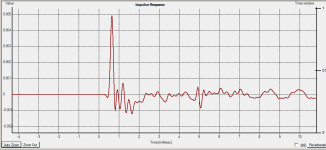
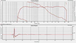
Here's the impulse response graph, but it's too small to be able to see what's going on.
And yes, these are in room measurements, without device correction.
I'm still finding my way around FuzzMeasure and not sure how to zoom in so tight!
Here's the impulse response graph, but it's too small to be able to see what's going on.
And yes, these are in room measurements, without device correction.
Attachments
Actually thinking about it, you probably don't want to limit the range that you are measuring over. Ideally run a full range sweep on each driver. That way you should see the higher frequencies as a very deninite spike. That spike is what gives you the best indication of where time zero is.
I'm not a mac guy so have never used FuzzMeasure But Try a full range (out to 20Khz) measurement and see if that is more inteligable 🙂
Tony.
I'm not a mac guy so have never used FuzzMeasure But Try a full range (out to 20Khz) measurement and see if that is more inteligable 🙂
Tony.
I was trying to recall why I set the sweep to such a narrow spectrum. Some searching revealed this article on aligning drivers that I read last week:
(new adventures in) ultra‑fi: time aligning speaker systems
Also, I now know how to zoom right in on those impulse response graphs. I'm thinking I should measure the two drivers separately, overlay the graphs and it SHOULD be easy to see the difference in response. I hope 🙂
(new adventures in) ultra‑fi: time aligning speaker systems
Also, I now know how to zoom right in on those impulse response graphs. I'm thinking I should measure the two drivers separately, overlay the graphs and it SHOULD be easy to see the difference in response. I hope 🙂
If (you should is my recommendation) you have your crossovers in place I would not limit the frequency sweep - at least not upwards as it might make the peak of each driver less easy to detect. Place mic in one position and let it be there for the whole session. Distance to speaker is somewhat of a problem - close you get less reflections which is good but at the same time you get a potential (small) timing error as compared to a given listening position but never mind this. Go for say something between 50-100cm but try to place the mic so that it is on the listening axis towards your listening position as I'm assuming you don't have a perfect omnidirectional speaker. Use trace colors that differ so you can identify them properly - they can be changed.
Now disconnect/mute all drivers but one. Do a sweep. Repeat for each driver so that you end up with one measurement per driver using their intended crossovers.
Now in FM (Fuzzmeasure), using *step response* display, select all measurements by cmd clicking on them - now you should see an overlay of your drivers (I suggest you do this only in pairs as it otherwise get to messy).
Now you have to decide if you want to align on the step onset or on the peak... I have not yet found any good source of info about which one to use. To me it seem logical that you would like to be energy optimized and that to me would mean the peak and that is what I have been using. In higher frequencies you should be able to get things within 1 ms irrespectively of you take the peak or onset and then it doesn't matter because the ear-brain can't do better then 1ms. In bass (< 300 hz) this is not true any longer and the jury is out (in my trail...).
Remember that when you change filters or compensations in the digital domain you introduce delay so if you add an new e.g. PEQ filter you timing will change. This way measuring the physical distances in a digital filter/compensation system does not make any sense. Ignore what the speaker looks like, study and trust your measurements 🙂
Enter your compensation for your identified delays and measure again so you get them in the right direction - I never seem to... 🙂
Now that a you have change the timing you might see response errors around your crossovers and this is due to that you might have been compensating for misalignment in time. If you think you have perfect time alignment but dips around a XO I suggest you widen the range for the driver and measure to see that it performs well at least an octave beyond its working area to be - if not that may be you problem.
And then there is still things that matter 😉 but this would be time alignment I suppose.
Good luck.
//
PS. This is how I have made it and got some good results I think... feedback is welcome.
Last edited:
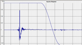
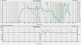
After TNT's comments above I decided to do a little experiment. I took some previous measurements of my MTM and the woofers they sit on. I highpassed at 200Hz and low passed at 400Hz and then looked at the impulse (first attachment). I then got rid of the lowpass at 400Hz and did a comparison (individually) of the MTM and the Woofer.
I think looking at either you would conclude that the time difference was 1ms, but with only the high passing it is much easier to make that conclusion.
Note that both measurements were taken at 66cm on axis with the tweeter. There is actually approx 78cm CTC between the woofer and the tweeter in this measurement so there is more than Z offset in this measurement. For time alignment purposes the measurement would need to be taken at a distance close to the listening distance (which was not the purpose of these measurements) but I think the attached shows why the higher frequencies help 🙂
Tony.
Attachments
Thanks TNT and Tony,
I've only had time for a quick measurement session since my last post, ( in which I hopefully got my high frequency and midbass horns reasonably well aligned. At least the delay I calculated was definitely not an unreasonable figure) but I hadn't read your latest comments unfortunately!
I've enlisted the help of a live sound engineer friend of mine who has plenty of experience with this sort of set up now though, so am waiting for his assustance. I will report back with our findings.
Jason.
- Status
- Not open for further replies.
- Home
- Design & Build
- Software Tools
- Help interpreting FuzzMeasure graph