Dear Fellows, I was wondering if anyone out there could help me with this problem. I'm currently a student but am not a electrial major so do bear with me for a while. he problem go as such.
We're to design a discrete component feedback with the following characteristics.
Single low input impedance ( <1 ohm) , Single high output impedance (> 1Mohm).
Output to supply a max instantaneous currect between +2A & -2A in any load resistance btw 0 to 10 ohms using +24, 0, -24 volt supply. Load is to be connected between out of amp and a 0.47 ohm resistor whose other end is connected to ground
Transfer function is -500/(1+s/10^5)
So far this is what has been found out, To get low input impedance and high output impedance current-sample current-sum is used. Also it is a low pass filter. So can anyone share some light on it or does anyone knows how from a transfer function you get the discrete componete???
Hi Edo
Have you got any details of the amp used, or can it be looked at as if it were a power OP-AMP ?
Regards
Charles
Have you got any details of the amp used, or can it be looked at as if it were a power OP-AMP ?
Regards
Charles
Edo,
you probably get better support if the wizards in the solid state amplifier board have a look on your problem.
I move your thread to Solid State. 🙂
you probably get better support if the wizards in the solid state amplifier board have a look on your problem.
I move your thread to Solid State. 🙂
Hi phase_accurate, actually the there is not standard op amp to be used. We're suppose to design it from scratch but I do have a picture of the circuit which can be used with a few mod to the first and second stage of the amp. could i email it to you???
Cheers
Cheers
dice45 said:Edo,
you probably get better support if the wizards in the solid state amplifier board have a look on your problem.
I move your thread to Solid State. 🙂
Thanks man, i tot i was in the solid state forum. But do have a question, since you have moved this how do i find it in future?????
Hi Edo
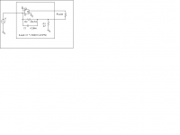
What you basically have to do is taking an inverting amplifier with high gain and implement current-feedback.
I attached a P-SPICE schematic. As ampifier I took (because I was a little lazy) a voltage controlled voltage source.
The final circuit's upper f3 is at 1/(2*Pi / 10^5) = 159.155 kHz.
In order to run stable into resistive loads, the amplifier's open loop f3 must be significantly higher than this.
Also inductive loads will be detrimental to stability (while capacitive loads might increase it).
If the gain of the amplifier is high enough it will try to keep the voltage at the input node at zero (as long as you don't run into saturation).
The value of the feedback resistor is then determined by
R2 = R1 * (Currentgain -1)
The capacitor C1 is determined by
C1 = 1/(2 * Pi * f3 * R2)
Hope this helps.
Regards
Charles
Attachments
HI phase_accurate,
Your diagram is the same as mine but however the transfer function which i need to get it AF(s) = -500/(1+s/10^5). In that case can i still use the same formula you gave??? I do not know what the s is in that eqn, thus i do not know how to get rid of it.
Therefore could you explain to me if you can, how from the transfer function could we get the R and the C??
Sorry about that phase_accurate,i'm abit slow with these stuff.
I think i figure out you were tryign to tell me. Af(s)=-500/(1+s/10^5) therefore the current gain is 500 right. This should be closed loop gain right. Then using the formula you gave i Got R2 and my C. but i do not know how did you manage to get the frequency and do you have any idea what the 10^5 is and the s???
I think i figure out you were tryign to tell me. Af(s)=-500/(1+s/10^5) therefore the current gain is 500 right. This should be closed loop gain right. Then using the formula you gave i Got R2 and my C. but i do not know how did you manage to get the frequency and do you have any idea what the 10^5 is and the s???
Hi Edo
s = j * 2 * Pi * frequency
The function you want to built is called PT1 in control terminology (at least in the German speaking area). It is basically an amplifier with first order lowpass characteristic.
For DC it's gain is 500 (in this case gain = Iout/Iin). It's upper corner (i.e. -3dB) frequency is determined by
f3=1/(2*Pi*R*C)=1/(2*P1/10^5)
Another way to write down the transfer function is:
H=A0 * 1/(1+s*T) = -500 * 1/(1+s*1/10^5) with T=R*C
Regards
Charles
Is that a 1 megohm output impedance you are
spec'ing? If so, compare to the 10 ohm load, you
are calling out an accuracy of .001% to be governed
by about 100 dB of feedback.
People often call out arbitrary specifications until they
get the quote, and then they refine their expectations.
What is it you are really trying to do?
spec'ing? If so, compare to the 10 ohm load, you
are calling out an accuracy of .001% to be governed
by about 100 dB of feedback.
People often call out arbitrary specifications until they
get the quote, and then they refine their expectations.
What is it you are really trying to do?
Trying to Design a discrete current amplifier which would amp a small signal say +-4 mv to a output of +-2A. It would include the differential input stage, the Current amplifier stage , and a unity-gain output stage. DO you happen to have a schmetic of such a circuit??? I only have been able to come across a voltage amplifier one.
I can find one, as can a number of people on this forum,
but does it require the 1 Megohm output impedance, which
might be a bit sticky, and when you say fast, how fast do
you mean, and why the 4 mV figure?
Help us help you. If we know what you're doing we will
be better able to help and probably more interested...
but does it require the 1 Megohm output impedance, which
might be a bit sticky, and when you say fast, how fast do
you mean, and why the 4 mV figure?
Help us help you. If we know what you're doing we will
be better able to help and probably more interested...
Sorry about the confusion Nelson, I'm abit confuse myself thus am asking around. However this is what i know so far. The Current amp we are to design goes with the transfer function AF(s) = -500/(1+s/10^5). Thus it is a low pass filter and it looks like the pic i've attached. Thanks to charles I who explained it to me I've got that part done. Thanks charles.
Next off dc gain is in this case 500 and since gain is given as Iout/Iin, Iin has to be 4mv to be about to give an output of 2A right thus that's where the 4mv came about. Output impedance just have to be close to 1Mohm or in this case as high as possible.
So far our design is as follows, there will be three stages the the differential input stage, the Current amplifier stage, and a unity-gain output stage. The current amplifier would feature a darlington configuation cause i dunno anything else that would give a current gain.
Also most differential input stage(using pi model) are found to be of high impedance Thus how does one incorporate a low input impedance using a differential input stage.
Does anyone have any comments???
Attachments

Hi Edo
Basically you can take an inverting VOLTAGE amplifier with high gain using this current-feedback topology to generate a current controlled current source. The higher the gain, the higher the output resistance (and also the faster it runs into saturation without apropriate load connected to it).
A low input impedance (theoretically 0.00 Ohms) is intrinsic to the above circuit topology. An inverting amlifier (unless overdriven) will always try to maintain O Volts at it's input and therefore have zero input impedance (whithout input series resistor of course).
Regards
Charles
P.S: You still owe us the answer what you will use this thing for 😉
Basically you can take an inverting VOLTAGE amplifier with high gain using this current-feedback topology to generate a current controlled current source. The higher the gain, the higher the output resistance (and also the faster it runs into saturation without apropriate load connected to it).
Also most differential input stage(using pi model) are found to be of high impedance Thus how does one incorporate a low input impedance using a differential input stage.
A low input impedance (theoretically 0.00 Ohms) is intrinsic to the above circuit topology. An inverting amlifier (unless overdriven) will always try to maintain O Volts at it's input and therefore have zero input impedance (whithout input series resistor of course).
Regards
Charles
P.S: You still owe us the answer what you will use this thing for 😉
Edo said:Sorry about the confusion Nelson, I'm abit confuse myself thus am asking around.
Edo, I wonder myself (like the rest of us) your application of this current amp? What is your load? What is the signal source? The basic idea is correct but sometimes the reality may surprise you.
The basic idea is correct but sometimes the reality may surprise you.
I fully agree 😎
Regards
Charles
The input Z is set by the feedback. As you say the input Z of a reasonable op-amp is very high.
I reckon, for R1>>R2, the input Z at the inverting input is:
Zin = R2 / [ 1 + R1.A/(R1+Rload) ]
Note that A is very frequency-dependent. Do a quick calc to convince yourself that the input Z is <1 ohm across the specified frequency range.
I reckon, for R1>>R2, the input Z at the inverting input is:
Zin = R2 / [ 1 + R1.A/(R1+Rload) ]
Note that A is very frequency-dependent. Do a quick calc to convince yourself that the input Z is <1 ohm across the specified frequency range.
Well charles, I dun really know what the application is. I'm also trying to figure out myself. Why i'm doing this is because it's an assignment and properly there is no application to it. Our lecturer just wants use to design it on paper from scratch thur theory so that we may understand Amp better i think.
Sorry if I made anyone think i was going to do it in hardware. I might once i get everything worked out but not at this moment.
Sorry 🙁
Sorry if I made anyone think i was going to do it in hardware. I might once i get everything worked out but not at this moment.
Sorry 🙁
- Status
- Not open for further replies.
- Home
- Amplifiers
- Solid State
- Help in designing of current output amp