I would appreciate some help to improve the power supply for the audioboard in my Arcam Delta 70.2 CD player. The audioboard has its own 12VA 15V + 15V transformer giving +/-20Vdc - which is filtered by CRC:- 1000uF-6R8-1000uF. This then feeds the regs; 7805/7905 for +/-5V, LM337 for -15V and a discrete +/-12V reg for I/V and opamps.
I was thinking changing the existing Tx to a 25VA torroidal unit and applying some additional filtering and / or a pre-reg. at 20V, to feed directly into the existing arrangement.
However, there are a few things I need advice on before proceeding. Firstly, the choice of transformer. I have a 15V + 15V 25VA torroidal - which would make an easy swap - but in Duncan Amps software it doesn’t bring much of a change to the conduction time or current peaks. I also have a 22V + 22V 25VA unit which seems to be more interesting - but I'm a bit concerned about the higher voltage causing some damage - especially if the load drops for some reason. Secondly, I’m not sure whether to use a pre-regulator or not.
Modelling some options in Duncan Amps PSUD2 and assuming a current draw of 150mA (to allow for excess) shows the following info:
Existing Power Supply:- 15V + 15V 12VA - diodes - 1000uF - 6R8 - 1000uF - regs.
Output voltage - 19.9V
Ripple voltage - 179mV
Conduction time - 3.8mS
Current Peaks - 0.5A
Option 1:- 15V + 15V 25VA - diodes - 1000uF - 6R8 - 1000uF - regs.
Output voltage - 21.5V
Ripple voltage - 196mV
Conduction time - 2.25mS
Current Peaks - 0.8A
This appears to be inferior to the original arrangement - but the addition of 3R3 - 470uF - 5R before the existing filter gives the following:
Output voltage - 19.0V
Ripple voltage - 83mV
Conduction time - 3.8mS
Current Peaks - 0.5A
Better - but not a huge improvement over the original.
Option 2:- 22V + 22V 25VA - diodes - 40R – (existing filter)1000uF - 6R8 - 1000uF - regs.
Output voltage – 18.9V
Ripple voltage - 133mV
Conduction time - 6.2mS
Current Peaks - 0.36A
This seems to be the best so far and only requires the addition of a 40R resistor. However, the no-load voltage could be as high as 36V. Will this cause any problems with the kill circuit etc?
Option 3:- 22V + 22V 25VA - diodes - 20R - 100uF - 20R – (existing filter)1000uF - 6R8 - 1000uF - regs.
Output voltage - 19.9V
Ripple voltage - 87mV
Conduction time - 5.5mS
Current Peaks - 0.4A
This also seems to be quite good and only requires the addition of 20R-100u-20R before the existing filter. However, the same no-load voltage concerns exist as above.
Option 4:- 22V + 22V 25VA - diodes - 10R - 220uF - 20R - 1000uF - (LM317/337 pre-reg set to 20V)
Output voltage - 24.67V
Ripple voltage - 251mV
Conduction time - 4.6mS
Current Peaks - 0.48A
I assume that the pre-reg would reduce the ripple to 251/10,000 = 0.0251mV. This could then be fed into the existing arrangement.
Any thoughts, comments or suggestion on this would be appreciated.
Attachments
Well, since no-one has bothered, I will respond, having some experience with the 78xx and 79xx "el-cheapo" regulators.
First, let me say that those numbers suck big hairy .... well, they are bad. I think the worst 78xx regulated supply I ever built had 5mV ripple. I have one now that is to be part of a transistor tester that currently displays an AC on the output that is just barely above the noise floor on our $$$$ fluke meters at work.
I think you need to break out a multimeter with an AC Volts range and take some measurements. I would be very surprised if the addition of some large, low-quality electrolytics on the input and output of your regulators wouldn't make such a big difference you'd poop your pants if you actually have nearly 180mV of ripple, currently! I would also be a little surprised if the ripple actually is that high (see 1st and 2nd sentences of this post) The tiny output cap on the top regulator inspired this post.
IMNSHO, a good regulated supply has a lot of filtration before AND after the regulator. A ton of caps first and that much noise out means to me that the CRC filter you have there is a waste, to be kind and refrain from vulgar vocabulary.
I Need to read this post and think some more.
/edit:
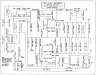
I reviewed the schematic there. Take measurements and confirm what ripple voltage you are actually putting out. Don't be surprised to see more noise on the output of the regulator that is regulated by another regulator first.
THEN
add 1000 or 2000 microfarads of cheap capacitors on the output of each regulator. Yes that's right. Some 25V 2000uF caps can't cost too much. Parallel them with the other caps that are currently there. Measure that.
If you just want some kicks, put similar 1000 or 2000uF caps on the input, paralleled with 0.1uF caps. Measure that, too.
That is likely to be as far as you want to go for less than $10 and 10 minutes. The next step up might be quite large in cost and time, compared to this first cheap and quite large one.
First, let me say that those numbers suck big hairy .... well, they are bad. I think the worst 78xx regulated supply I ever built had 5mV ripple. I have one now that is to be part of a transistor tester that currently displays an AC on the output that is just barely above the noise floor on our $$$$ fluke meters at work.
I think you need to break out a multimeter with an AC Volts range and take some measurements. I would be very surprised if the addition of some large, low-quality electrolytics on the input and output of your regulators wouldn't make such a big difference you'd poop your pants if you actually have nearly 180mV of ripple, currently! I would also be a little surprised if the ripple actually is that high (see 1st and 2nd sentences of this post) The tiny output cap on the top regulator inspired this post.
IMNSHO, a good regulated supply has a lot of filtration before AND after the regulator. A ton of caps first and that much noise out means to me that the CRC filter you have there is a waste, to be kind and refrain from vulgar vocabulary.
I Need to read this post and think some more.
/edit:
I reviewed the schematic there. Take measurements and confirm what ripple voltage you are actually putting out. Don't be surprised to see more noise on the output of the regulator that is regulated by another regulator first.
THEN
add 1000 or 2000 microfarads of cheap capacitors on the output of each regulator. Yes that's right. Some 25V 2000uF caps can't cost too much. Parallel them with the other caps that are currently there. Measure that.
If you just want some kicks, put similar 1000 or 2000uF caps on the input, paralleled with 0.1uF caps. Measure that, too.
That is likely to be as far as you want to go for less than $10 and 10 minutes. The next step up might be quite large in cost and time, compared to this first cheap and quite large one.
Hi Stocker
Thanks for your reply and input.
Just to clarify - the ripple figures that I mention above are obtained from DuncanAmps PSUD2 simulation software - and are for the output of the passive part of the supply BEFORE any regulators.
I understand that I can reduce the ripple significantly with the addition of more capacitance - but this is at the expence of conduction time and current peaks.
- Status
- Not open for further replies.