Hello everyone, thanks for reading my question.
I am working on an old Crest Audio 8001 amp. One channel is down and after taking some readings on all the resistors I am replacing all the faulty ones one by one(alongside other parts of course). There are a few on the PCB that I can not identify in terms what material (carbon, metal etc) they are made of as well as what power they would be. They are approximately 9mm long and brownish in color.
I am wondering are there any real significance of this at all ? Can I replace these with any type with of course the same resistance, tolerance and power ?
Being a high powered class H amp this, i would like to make sure I choose the right components and wont be let down on a 20p resistor. Your advice will be much appreciated !
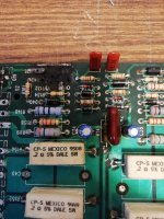
I am attaching a couple of photos with the PCB the resistors in question are the ones in the yellow rectangles.
I am working on an old Crest Audio 8001 amp. One channel is down and after taking some readings on all the resistors I am replacing all the faulty ones one by one(alongside other parts of course). There are a few on the PCB that I can not identify in terms what material (carbon, metal etc) they are made of as well as what power they would be. They are approximately 9mm long and brownish in color.
I am wondering are there any real significance of this at all ? Can I replace these with any type with of course the same resistance, tolerance and power ?
Being a high powered class H amp this, i would like to make sure I choose the right components and wont be let down on a 20p resistor. Your advice will be much appreciated !
I am attaching a couple of photos with the PCB the resistors in question are the ones in the yellow rectangles.
Attachments
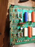
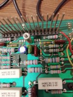
Just look like standard 5% carbon film types of different power ratings, small ones likely 1/4W, larger ones 1/2W or 1W
Still available from various suppliers. Length can be the same but diameter changes for different power ratings for some parts.
Still available from various suppliers. Length can be the same but diameter changes for different power ratings for some parts.
Yup, bog standard carbon film (0207 size by the look of it). You can replace them with metal film without any issues.
Vishay MRS25 or TE LR1 are cheap, good quality and rated for 0.6W
Vishay MRS25 or TE LR1 are cheap, good quality and rated for 0.6W
Um, are you measuring these while still in circuit to decide to replace them? In many situations of not most, resistors in circuit will have parallel parts in the circuit causing them to "read low".
@ohdsp @DontHertzMe thanks for the swift answer and the useful comments.
@Enzo I have the circuit diagram I am taking the resistance values from there. I have removed the resistors for test - or at least one side of them. The photos above are from the working side of the amp.
@Enzo I have the circuit diagram I am taking the resistance values from there. I have removed the resistors for test - or at least one side of them. The photos above are from the working side of the amp.
@ohdsp @DontHertzMe just looked at what I have. I have Metal film or Carbon oxid resistors that match the values of the above mentioned brownish ones. Will I be ok to use those ?
What is the significance of using one or the other type ?
What is the significance of using one or the other type ?
Also one more question:
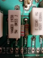
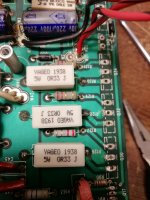
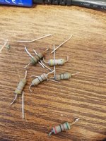
I got some 2.2ohm 1w fusible resistors to replace a couple of these but when I look at them although they have the same power rating and resistance as the ones in the circle they just look a lot "weaker". The leaders are smaller diameter and the body of the resistor is little slimmer smaller as well.
Please see the attached photo one with the resistors next to each other and one in circuit. R127 R129.
Shall I look for better quality ones ? I am afraid as this is a fusible resistor the new ones will just burn out for no reason at one point under heavy load. Does this make sense? Is there such a thing as one resitor better than the other of the same ratings ? Are there fake ones lurking around ? ( i know there are plenty of fake transistors , bough quite few unfortunately )
Attachments
With due respect you will never ever repair that amplifier working that way.
Pulling 1000 components and measuring them one by one against schematic values is slow, maddening and guarantees nothing.
You need to plug that amp into an outlet, through a lamp bulb limiter or slowly raising voltage with a Variac, and measure **voltages**.
Abnormal voltages will direct you to problematic areas and THERE, according to SYMPTOMS, you start guessing possible motives and measuring values, confirming or not your guesses.
AFTER you got DC voltages right, you start functional tests, you inject audio and listen/scope output, looking at abnormalities.
Resistors in particular, are presumed good unless heavily toasted, plain burnt or cracked, none of which I see in your boards.
Suspect semiconductors instead, but again, wrong voltages will lead you to them.
What you are doing now amounts ton "looking for the car keys under the lamppost" ... 3 blocks away from your car.
You know how to measure resistors, not how to test capacitors or semiconductors, nor get voltage readings and guess possible cause, so you stick to the first.
Sadly that´s not enough, by far.
Last edited:
I am by no means an expert at all and probably will need further help when completed the stage where I am at the moment indeed. Yet known wrong components needs to be replaced and no point plugging the amp in until I know there are components that are faulty, is that correct ? The amp had visibly faulty output transistors as in they exploded and parts were missing. Also one part of the PCB is burnt due to a failing diode or resistor. Not sure which one it was as they were right next to each other.
Would I be plugging in the amp as is, knowing the resistors are burnt the transistor is missing a piece? Please explain id like to understand.
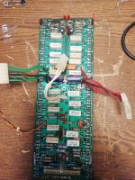
I went ahead and did what everyone says to do in this case. Tested all the output transistors ( 5 pair faulty of the 11 pair) and large ceramic resistors quite a few were open of those too. Replaced the ceramic resistors and replacing other resistor that are faulty (couple of the aforementioned 2.2ohm fuse ( the ones my question is above here ) ones and moving onto the part where the PCB is burnt checking/ replacing parts that are faulty. Attaching some photos just so readers have an idea.
This is where I am, indeed I dont deny I may have been going down the wrong path but this is where I am at the moment - how do I move forward?
Would i want to put faith in the "weak" looking 2.2 ohm resistors. This is important question and blocker for me atm. Ordering new ones take time and from any decent supplier will cost a fortune as ordering only them will incur a charge for postage which is normally quite significant compared to their value.
I am here to learn please advise me accordingly.
Would I be plugging in the amp as is, knowing the resistors are burnt the transistor is missing a piece? Please explain id like to understand.
I went ahead and did what everyone says to do in this case. Tested all the output transistors ( 5 pair faulty of the 11 pair) and large ceramic resistors quite a few were open of those too. Replaced the ceramic resistors and replacing other resistor that are faulty (couple of the aforementioned 2.2ohm fuse ( the ones my question is above here ) ones and moving onto the part where the PCB is burnt checking/ replacing parts that are faulty. Attaching some photos just so readers have an idea.
This is where I am, indeed I dont deny I may have been going down the wrong path but this is where I am at the moment - how do I move forward?
Would i want to put faith in the "weak" looking 2.2 ohm resistors. This is important question and blocker for me atm. Ordering new ones take time and from any decent supplier will cost a fortune as ordering only them will incur a charge for postage which is normally quite significant compared to their value.
I am here to learn please advise me accordingly.
Last edited:
- Home
- Design & Build
- Parts
- Help! Identifying resistor type