This might be a long shot, but I'm looking to see if anyone can identify an output transformer.
Back in 1993 I purchased the parts to build a stereo pair of Mullard 5-20 amps (with solid state rectifiers). I was in the UK and it's possible all the parts came from/via Maplin (this was a year before they published their Millenium 4-20 amp though). All the tubes/valves are from Chelmer Valve Company, including a nice set of matched EL34s.
I remember not being able to find suitable power transformers, but Maplin sold kits where you could "wind your own". They came with a standard 240v primary and you could wind whatever you needed on the secondary. I remember it was kind of fun interleaving the EI core. I ended up ditching these though because I moved to the US and the 240v primaries weren't going to do me any good. Everything else got packed up and came with me... and then stashed away in the bottom of a drawer and forgotten about.
Fast forward 25 years and I am finally getting round to finishing the build 😱 There is one problem though... I have a pair of output transformers that I always assumed had the ultra-linear taps. I don't have any documentation on them, so I used my multimeter to work out the windings. It appears there are two separate primary windings (yellow-red and yellow-black wires) and a secondary, which I assume is 0-4-8 ohms (black-blue-red wires). The primaries have no UL taps, they are just standard push-pulls.
I'm not sure if I knew this when I purchased them (I don't think so though). Either way... it's probably a bit too late to return them 😛 I can modify the circuit and was thinking of putting in a "triode/pentode mode" switch to switch g2 on the EL34 between the HT and anode (via the existing 1k resistor). No ultra-linear mode though 🙁
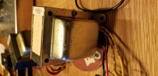
I attached photos. The part number is "4-SK-797". This doesn't look like a Maplin part number. The Millenium OP transformer part number was DM53H, and the power transformer was DM54J. The sticker describes them as "25W/6K/EL34 PP", which is pretty self explanatory.
Does anyone in the UK have any additional ideas/info on these?
Thanks,
Alastair
Back in 1993 I purchased the parts to build a stereo pair of Mullard 5-20 amps (with solid state rectifiers). I was in the UK and it's possible all the parts came from/via Maplin (this was a year before they published their Millenium 4-20 amp though). All the tubes/valves are from Chelmer Valve Company, including a nice set of matched EL34s.
I remember not being able to find suitable power transformers, but Maplin sold kits where you could "wind your own". They came with a standard 240v primary and you could wind whatever you needed on the secondary. I remember it was kind of fun interleaving the EI core. I ended up ditching these though because I moved to the US and the 240v primaries weren't going to do me any good. Everything else got packed up and came with me... and then stashed away in the bottom of a drawer and forgotten about.
Fast forward 25 years and I am finally getting round to finishing the build 😱 There is one problem though... I have a pair of output transformers that I always assumed had the ultra-linear taps. I don't have any documentation on them, so I used my multimeter to work out the windings. It appears there are two separate primary windings (yellow-red and yellow-black wires) and a secondary, which I assume is 0-4-8 ohms (black-blue-red wires). The primaries have no UL taps, they are just standard push-pulls.
I'm not sure if I knew this when I purchased them (I don't think so though). Either way... it's probably a bit too late to return them 😛 I can modify the circuit and was thinking of putting in a "triode/pentode mode" switch to switch g2 on the EL34 between the HT and anode (via the existing 1k resistor). No ultra-linear mode though 🙁
I attached photos. The part number is "4-SK-797". This doesn't look like a Maplin part number. The Millenium OP transformer part number was DM53H, and the power transformer was DM54J. The sticker describes them as "25W/6K/EL34 PP", which is pretty self explanatory.
Does anyone in the UK have any additional ideas/info on these?
Thanks,
Alastair
Attachments

" and a secondary, which I assume is 0-4-8 ohms (black-blue-red wires)."
Given its age, I would guess it is more like 0-8-16 ohms
Given its age, I would guess it is more like 0-8-16 ohms
Thanks for the replies. I was able to track down Mike Holmes NOS listing of the Danbury PP OP transformers and it doesn't look like it's one of those. The Danbury part numbers are all VTxxxx, so I think this may have come from someone else.
Valve Push-Pull Output Transformers
Valve Push-Pull Output Transformers
25 years ago there would have been more companies in the UK making valve audio transformers. In some cases a shop selling them would use their own part number and not mention who made them.
You know the primary is 6KCT.
Feed say 12V 100Hz AC into the primary, use DVM to measure the secondaries, do math, you have secondary impedances.
Feed say 12V 100Hz AC into the primary, use DVM to measure the secondaries, do math, you have secondary impedances.
No ultra-linear mode though 🙁
It's a non-issue. Full pentode mode, with g2 B+ regulated at a fraction of anode B+, works very well. 😉
As for power transformers, 2X (1 trafo/monoblock) of this affordable AnTek toroid should be quite OK.
Thanks for the hint PRR. It made me realize I can just measure the inductance, take the square root and get an idea of the turn ratios.
Normalizing the numbers and setting the smallest inductance to 1 (black and blue) I get the black to red at around 4, and blue to red at around 3. Since the red would be the ground (in order to generate the inverted signal for negative feedback), then the blue would be 3x and the black would be 4x.
Assuming the red to black is 8 ohms, then the red to blue would be 6 ohms. Was 0-6-8 secondary windings a thing?
Inductance does not add like resistance, so 1+3 does not equal 4. 1+3 should be around 5.
I would not assume that red is ground. First, this would be an odd colour choice - black is more likely. Second, whether this gives negative or positive feedback would depend on how the primary is wired and how the rest of the circuit is wired. However, 0-6-8 could be correct, as I seem to recall a trend back then for woofers to have lower impedance in order to boost output so a nominal 8 ohm speaker could actually be less than this.
I would not assume that red is ground. First, this would be an odd colour choice - black is more likely. Second, whether this gives negative or positive feedback would depend on how the primary is wired and how the rest of the circuit is wired. However, 0-6-8 could be correct, as I seem to recall a trend back then for woofers to have lower impedance in order to boost output so a nominal 8 ohm speaker could actually be less than this.
Inductance does not add like resistance
The numbers were turns ratios, where the turns ratio is the square-root of the inductance ratio. I measured the inductances as:
Secondary black-blue = 1.1mH
Secondary blue-red = 7.5mH
Secondary black-red = 16.5mH
Primary (both) = 3H
If the windings are oriented so that the black-red on the primary is in the same direction as the black-red on the secondary, then if the red of the primary is "pointing up" in the circuit, then the red of the secondary would be the one connected to ground.
How are you "measuring inductance"?
Iron-core windings will give inductance all over the place, depending on test signal level and other factors. If you use a generic induct-o-meter testing at 1KHz, the core is just-barely involved. Seriously: heater transformer. 50/60Hz. Put a 1 Ohms 1/2 in series so if something shorts you don't kill a good heater transformer. The primary can surely stand 6VAC or 12VAC. This used to be a problem since the secondary could be tenths of an ohm and in the dubious zone on most needle-meters; modern DMMs will resolve mV at power frequency. It makes little matter that the OT may not be rated for 50Hz; the low-low-Z of the heater transformer will get real voltage in there despite lack of inductance. The low signal level keeps it out of nonlinearity.
Iron-core windings will give inductance all over the place, depending on test signal level and other factors. If you use a generic induct-o-meter testing at 1KHz, the core is just-barely involved. Seriously: heater transformer. 50/60Hz. Put a 1 Ohms 1/2 in series so if something shorts you don't kill a good heater transformer. The primary can surely stand 6VAC or 12VAC. This used to be a problem since the secondary could be tenths of an ohm and in the dubious zone on most needle-meters; modern DMMs will resolve mV at power frequency. It makes little matter that the OT may not be rated for 50Hz; the low-low-Z of the heater transformer will get real voltage in there despite lack of inductance. The low signal level keeps it out of nonlinearity.
> The actual inductance values aren't too meaningful, it's their ratios that's important.
Of course. But measuring individually, the volts per turn and the core flux is different on each winding.
Of course. But measuring individually, the volts per turn and the core flux is different on each winding.
PRR makes an important point, and those inductance values do not sound even close to correct, so you can't calculate the ratios from them.
Use a known ac voltage across the entire primary and measure the voltages across each secondary tap.
Use a known ac voltage across the entire primary and measure the voltages across each secondary tap.
OK.drmeasle said:The numbers were turns ratios,
Clearly something is wrong. Closely-coupled 1.1mH and 7.5mH windings would give 14.3mH for a series connection. Real life would give a slightly lower figure because the coupling cannot be perfect; you get 16.5mH.I measured the inductances as:
Secondary black-blue = 1.1mH
Secondary blue-red = 7.5mH
Secondary black-red = 16.5mH
- Status
- Not open for further replies.
- Home
- Amplifiers
- Tubes / Valves
- Help identifying EL34 OP Transformer (from UK)