Hi All,
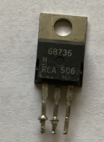
Can anyone help identifying these transistors?
My tester identifies them as Darlingtons.
But what I'm after is their specs.
Can they be used for audio?
Happy New Year
Andy
Can anyone help identifying these transistors?
My tester identifies them as Darlingtons.
But what I'm after is their specs.
Can they be used for audio?
Happy New Year
Andy
Attachments

Last edited:
Hi All,
Can anyone help identifying these transistors?
My tester identifies them as Darlingtons.
But what I'm after is their specs.
Can they be used for audio?
Happy New Year
Andy
Just a minute... crystal ball warming up... it might help if we know what we are looking at 😉
I'm not familiar with either of those tbh. We used to see a lot of 'in house' numbers in older TV chassis (R numbers and so on but I've not seen those before.
Then no Darlingtons .
Where did you pull them from?
"Should" be similar to, say,TIP31/32 and usable in same circuits.
How many do you have?
Where did you pull them from?
"Should" be similar to, say,TIP31/32 and usable in same circuits.
How many do you have?
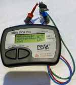
Forward bias the B-E junction from a PSU or battery with a 2k2 series limiting resistor and see what the B-E junction drops. If it is around 1.1v or higher then it's probably some kind of Darlington.
From what was said.
I see Vbe 1.15V and Beta 60.
Could that be a Darlington and the 60 from reverse Beta.
Reversing emitter and collector keep a PNP being a PNP, as well a NPN becomes a NPN. However, gain is much lower.
As can be checked on BJT Spice model
BF ( forward ) and BR ( reverse ).
I see Vbe 1.15V and Beta 60.
Could that be a Darlington and the 60 from reverse Beta.
Reversing emitter and collector keep a PNP being a PNP, as well a NPN becomes a NPN. However, gain is much lower.
As can be checked on BJT Spice model
BF ( forward ) and BR ( reverse ).
A Darlington has only one junction between base and collector (the one of the first transistor), so if emitter and collector were reversed, you should see a much lower voltage.
I think the combination of VBE and hFE makes sense if the second transistor has a resistor between its base and emitter and the test current is only just too small to turn on the second transistor.
I think the combination of VBE and hFE makes sense if the second transistor has a resistor between its base and emitter and the test current is only just too small to turn on the second transistor.
They do sound like some form of Darlington but given that they are an unknown and that new ones are cheap it's not really worth the risk to use them... you just don't know.
Hi.Can anyone give information about these transistors?Thanks
Attachments


Last edited:
APT makes mosfets and IGBTs. From the gate side you can’t really tell the difference. You could try pushing about 10 amps thru one, (1 ohm resistor array, 12 volt battery) by applying +12 on the gate. If you drop more than half a volt or so across the drain/source (collector/emitter) it’s an IGBT. If it’s closer to half a volt, it’s a “high voltage” mosfet. If it’s a low voltage unit, it will be closer to a tenth. Short gate to source, and check it with a diode test backwards to see if it’s got antiparallel diode. Mosfets always do, IGBT’s sometimes.
As far as the original darlingtons are concerned, the base-emitter resistors leak enough current to affect the hfe readings. Data sheets will show very low gain at low current even if the intrinsic transistor gain is higher.
As far as the original darlingtons are concerned, the base-emitter resistors leak enough current to affect the hfe readings. Data sheets will show very low gain at low current even if the intrinsic transistor gain is higher.
- Home
- Design & Build
- Parts
- Help Identify These Transistors