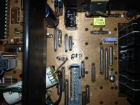
The diode (at position "183" of attached PCB image. It's sitting vertically, between two jumpers, next to jumper 219, parallel to vertical black chassis divider):
It's small, white with a black (cathode) and another green band.
It sits on the -5v rail, near the 7905 reg. One side (cathode) ties to -5v pin of a TDA1541 dac. The other side goes to -5v rails/pins of various servo chips/transistors.
The diode drop about 0.5v .So, I'm assuming it's being used to "further drop/regulate" voltage to the TDA1541A (where the -5 rail measures -4.5).
On the anode side of the diode, all the servo components get all -5.0v.
Problem is, the TDA1541A has a min. -5v rail requirement of -4.5v. And I've seen this value as high as -5.6v on good, working, factory-original CD players.
Again, help me identify the diode (parameters) so I can look for a replacement that has lower Vfd.
Attachments
Last edited:
Can you explain what problem occurred or what is not working on the device? It doesn't really make sense that you are needing to change the diode yet it does not appear to have failed.
I think he is hoping for a flash of inspiration from someone
") as I get the feeling hollowman isn't to impressed by the replies so far received in another thread/s. But I could be wrong...
as I get the feeling hollowman isn't to impressed by the replies so far received in another thread/s. But I could be wrong...First it fell off the table, well I think it fell off a table although it may have had a soft landing (the diode puts in an appearance around post #76):
Philips (Marantz) CD-60 not spinning up
Replacing CD laser -- laser power and/or focus trim
Better laser amp transistor than BC338?
The Marantz CD60 serv. man. shows the position that diode is in (183) to be a jumper, not a diode. Methinks it was some sort of last-minute tweak to the TDA1541's -5v power-rail.
Also, it may serve to "isolate" the TDA1541 from other ICs powered by the 7905 reg.
Also, it may serve to "isolate" the TDA1541 from other ICs powered by the 7905 reg.
I laid all out in the OP, dude. I know, I know ... the habit nowadays is TL;DR.Can you explain what problem occurred or what is not working on the device? It doesn't really make sense that you are needing to change the diode yet it does not appear to have failed.
Well, he already said that falling off the table was not that important, and that he does not see anything broken, so ....
EDIT: as of:
EDIT: as of:
that will certainly motivate members to try to helpI laid all out in the OP, dude.
Last edited:
Please point to the exact post where I supposedly said the above.Well, he already said that falling off the table was not that important, and that he does not see anything broken, so ....
EDIT: as of: that will certainly motivate members to try to help
The CD60 did not fall off a table; it tipped off to its side (about 1 foot) from a low shelf on to a matted/carpeted floor. And I suggested that was not "important"? Really?
Mooley, in his summary post above, was POORLY summing up the etiology of the CD60 thread.
In any case:
The... Philips (Marantz) CD-60 not spinning up
... thread is long, has a lot of detail, and not bedtime reading. But if you're a techie, and are up to it, it may be worth a lookover. Warning: you may find it humiliating, humbling or disturbing
Thx.It is definitely from Philips, thus from the body colour it is either a BAWxx or a BATxx.
Since it is a small body, it must be a BAT, and from the color code (gray/green), it is a BAT85, a small schottky diode.
Again, it's not in the PDF schematic. The 183 position is shown with a jumper (not diode). Must be some kind of last-min. addition, never making it into the "final draft".
Now all I need is on of these guys with the min. Vfd possible (Wiki suggests this maybe 150mV as min. for Schottky ???).
Last edited:
Vfd varies tremendously in relation to the current being drawn through the device. The diode was obviously built into the final design, and the final design also used a -5 rather -6 volt initial supply.
Altering the original design isn't really the way to fixing your fault imo, although trying things can sometimes be a useful handle into a problem.
Have you tried shorting the diode to see if the fault changes ?
You could also use a normal diode to 'lift' the -5 volts to around -5.6 and see if that has any effect.
At the end of the day, your working player was fine until it fell, and after which it was faulty........
The low voltage drop (0.5V) also indicates it is schottky diode.It is definitely from Philips, thus from the body colour it is either a BAWxx or a BATxx.
Since it is a small body, it must be a BAT, and from the color code (gray/green), it is a BAT85, a small schottky diode.
BAT85 is a very good guess.
Huh?
Also, in the other thread, I noted that I did replace the 1541's -5v rail 5-ohm "safety R" to 0.5-ohm. That brought the voltage up -4.5v (up from -4.3). Noise issue remains.
I'm limited to a MAX of -5v per the stock, factory-original 7905. See OP of this thread. Yes, the PDF schematic has a 7906, not 7905. But my Philips CD60 uses a 7905.You could also use a normal diode to 'lift' the -5 volts to around -5.6 and see if that has any effect.
Also, in the other thread, I noted that I did replace the 1541's -5v rail 5-ohm "safety R" to 0.5-ohm. That brought the voltage up -4.5v (up from -4.3). Noise issue remains.
No improvement!
Bridged it, which brought up Vdd1 to -4.9v.
Noise issue remains!
Straight, white line underneath (like jumpers).Is there any component symbol (white rectangle) or just a straight line under the diode? In the latter case just bridge it
Bridged it, which brought up Vdd1 to -4.9v.
Noise issue remains!
Eh
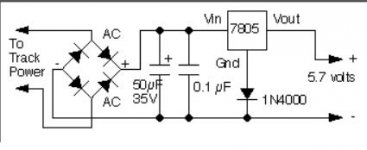
Its a standard technique to lift the output a three terminal reg. This shows a 7805, the 7905 would have the diode fitted the other way around (remember the pin outs are different for 79 regs). Use a 1N4148 type diode (small signal type as only a tiny current flows in it). The reg output is raised by the forward voltage of the diode. It works well... and you can use zeners (6v8 or 7v1 Zener) to make for example a 12 volt reg using a 7805, or you can use a resistor/s and make it variable, or you can add a transistor to the ground lead and make a super adjustable regulator with terrific regulation.
Here is the simple way. This adds around 0.65 volts to the reg output.
I'm limited to a MAX of -5v per the stock, factory-original 7905. See OP of this thread. Yes, the PDF schematic has a 7906, not 7905. But my Philips CD60 uses a 7905.
Also, in the other thread, I noted that I did replace the 1541's -5v rail 5-ohm "safety R" to 0.5-ohm. That brought the voltage up -4.5v (up from -4.3). Noise issue remains.
Its a standard technique to lift the output a three terminal reg. This shows a 7805, the 7905 would have the diode fitted the other way around (remember the pin outs are different for 79 regs). Use a 1N4148 type diode (small signal type as only a tiny current flows in it). The reg output is raised by the forward voltage of the diode. It works well... and you can use zeners (6v8 or 7v1 Zener) to make for example a 12 volt reg using a 7805, or you can use a resistor/s and make it variable, or you can add a transistor to the ground lead and make a super adjustable regulator with terrific regulation.
Here is the simple way. This adds around 0.65 volts to the reg output.
Attachments
- Status
- This old topic is closed. If you want to reopen this topic, contact a moderator using the "Report Post" button.
- Home
- Amplifiers
- Power Supplies
- Help identify diode!