Hi,
Could you guys give me a help about how to proper fold a horn?
I saw some information about it some weeks ago but I'm not able to find it.
If possible lets take the image below as example, so if i want to fold a horn in a 90 degree, how is the proper way to link those two parts in order to avoid path restriction?
Direct image link: https://s14.postimg.org/79nq3floh/How_to_fold.png
Could you guys give me a help about how to proper fold a horn?
I saw some information about it some weeks ago but I'm not able to find it.
If possible lets take the image below as example, so if i want to fold a horn in a 90 degree, how is the proper way to link those two parts in order to avoid path restriction?
An externally hosted image should be here but it was not working when we last tested it.
Direct image link: https://s14.postimg.org/79nq3floh/How_to_fold.png
opps,
just found it, the right answer is linking the segment middle over middle.
Horn Folding in Sketch-Up - AVS Forum | Home Theater Discussions And Reviews
just found it, the right answer is linking the segment middle over middle.
Horn Folding in Sketch-Up - AVS Forum | Home Theater Discussions And Reviews
Soho 54 who Posted in the AVS thread you mentioned developed a better method that he posted here
http://www.diyaudio.com/forums/subwoofers/171747-spreadsheet-folded-horn-layouts-2.html#post2270926
My last thoughts on folding horns are detailed here
http://www.diyaudio.com/forums/subw...3d-model-automatic-folding-2.html#post4849142
I tend to model the speaker as a folded horn and then use the dimensions generated by the geometry to unfold the horn. I use a parametric CAD program to draw the speaker so that any changes update the unfolded horn shape automatically. The speaker drawing is then adjusted to get the best unfolded shape.
Regards Xoc1
Hi,
What Xoc1 said, only difference is that I have to do it the hard way, no parametric CAD program. Start w/ the external size, draw in the horn, unfold...repeat. Practice really helps. 🙂
Regards,
What Xoc1 said, only difference is that I have to do it the hard way, no parametric CAD program. Start w/ the external size, draw in the horn, unfold...repeat. Practice really helps. 🙂
Regards,
At the fold the area changes.
You have A1 at the end of the first section.
A2 at the middle meeting points.
A3 at the start of the next section.
These are along the horn length and should not be the same. You can arrange for them to follow the horn expansion rate. This requires the A2 area to be reduced very significantly to end up at a value somewhere between A1 & A3 . Your "link result" shows the enlargement due to A2 being too big.
Between A1 and A2 you will have an area variation as the wave travels along the horn. You don't want a constriction (smaller area). That adversely affects the way the horn performs. The horn will better tolerate a small increase in area as long as that increase is kept low.
These variations can be analysed using Hornresp.
You may find that for a long wavelength horn that it becomes insignificant.
Last edited:
WoW parametric CAD program is really cool.
I'm doing the hard way too, it take huge amount of time and once the segments are linked if one dimension is not as desired I need to redo everything 🙁
I already defined the horn length, the compression ratio and the angle, now I'm trying to change SS15 to fit the ideal horn I simulated for my driver. The results is promising and will allow me to reach all target i need.
I must try looking into using Onshape CAD as it offers parametric modelling for free.
https://www.onshape.com/
That's if I get enough free time!
https://www.onshape.com/
That's if I get enough free time!
Is the fold below right?
If yes i will adjust the simulation and go to the next steps as adding braces, etc.
I loose small length close to S1, highlight in brack, that reduces insignificantly the compression ratio. The good part is the total length gained highlighted in dark green and dark blue that will help with low frequencies.
Cab width = 55cm
Total volume = 261,4 L
An externally hosted image should be here but it was not working when we last tested it.
It will take too much time to check Xoc1 technique, to do it parametric sketch in needed so SolidWork is on-going 🙂
In a while I performed a fast test to compare what I did and what some guys do. So please let your feedback.
The first image indicate the same horn segments with 2 different link.
The left one (green/blue) the horn was splitted into 2 segment direct linked.
The right one (red/yellow) the horn was splitted into 5 segments, 3 of them have equal length (2cm) and they ware used to link the other 2 segments. Looks like if split even more the segments keeping the total length (6cm in this case) the result will be perfect rounded path.
The most important thing and the obvious one is that the total horn length is absolutely equal in both case. Independent from the shape as long the segments are linked each other the result regarding total length will always be the same.
The second image overwrite both images and in this case we can see some changes in terms of proportion.
The green/blue is shorter at X and Y direction and the red/yellow is the opposite. It's like a compensation.
From simulation to draw fold horn it still hard to conclude without experience from my side.
In a while I performed a fast test to compare what I did and what some guys do. So please let your feedback.
The first image indicate the same horn segments with 2 different link.
The left one (green/blue) the horn was splitted into 2 segment direct linked.
The right one (red/yellow) the horn was splitted into 5 segments, 3 of them have equal length (2cm) and they ware used to link the other 2 segments. Looks like if split even more the segments keeping the total length (6cm in this case) the result will be perfect rounded path.
The most important thing and the obvious one is that the total horn length is absolutely equal in both case. Independent from the shape as long the segments are linked each other the result regarding total length will always be the same.
An externally hosted image should be here but it was not working when we last tested it.
The second image overwrite both images and in this case we can see some changes in terms of proportion.
The green/blue is shorter at X and Y direction and the red/yellow is the opposite. It's like a compensation.
From simulation to draw fold horn it still hard to conclude without experience from my side.
An externally hosted image should be here but it was not working when we last tested it.
That method uses a right-angled path through the bends, which has been shown to be incorrect (it over-estimates the length of the horn). The error is fairly small, but does increase based on the number of folds, and the size of each fold.
I think the green sections when summed will slightly over estimate the horn path.Is the fold below right?
If yes i will adjust the simulation and go to the next steps as adding braces, etc.
I loose small length close to S1, highlight in brack, that reduces insignificantly the compression ratio. The good part is the total length gained highlighted in dark green and dark blue that will help with low frequencies.
Cab width = 55cm
Total volume = 261,4 L
An externally hosted image should be here but it was not working when we last tested it.
The horn path may be closer estimated by curving around the corners rather than taking the longer straight paths.
I must try looking into using Onshape CAD as it offers parametric modelling for free.
https://www.onshape.com/
That's if I get enough free time!
Also check out the opensource FreeCad parametric CAD program
DIY?
Hi LORDSANSUI,
You can apply the 'advanced centerline method' that just-a-guy explained to you to check your fold.
Regards,
Hi LORDSANSUI,
You can apply the 'advanced centerline method' that just-a-guy explained to you to check your fold.
Regards,
Hi Oliver,
Could you send me the link for "advanced centerline method"?
The only information I found was one image from Soho54 without any other information, just looking to the image is possible to see that he uses the link with 3 segments, visually the segments are not equal in terms of length so maybe the angle between them are. Maybe the complete method are splitted between some threads.
Other image I found, was from Xoc1, with a lot of constrains that is just possible with parametric software and looks like it is more oriented to unfold horn them to fold one.
Could you send me the link for "advanced centerline method"?
The only information I found was one image from Soho54 without any other information, just looking to the image is possible to see that he uses the link with 3 segments, visually the segments are not equal in terms of length so maybe the angle between them are. Maybe the complete method are splitted between some threads.
Hmm... something seems off. EDIT: I read this wrong.
Here is a picture with a bend made up of three 25cm squares, and the lengths derived from the most popular methods, and my own in the middle. 😀
The Square-root method comes in at 70.71.
Try running this through your program to see what it comes up with.
Other image I found, was from Xoc1, with a lot of constrains that is just possible with parametric software and looks like it is more oriented to unfold horn them to fold one.
This is the way I did it.
The lines are always connected to the midpoints of the width lines.
The 3 path lines around an approx 90 deg bend are equal
The first width line at the beginning of the bend is perpendicular to the preceding path line.
The final width line is perpendicular to the outside face.
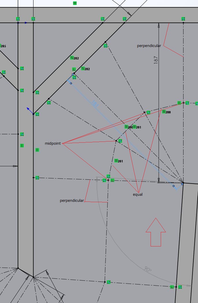
Attached screen grab shows a Solidworks path sketch as used to generate the unfolded path length. I turned on the sketch relation symbols (The green marks)
Extra labelling added with red annotation lines.
Hope that helps!
Xoc1
Hi LORDSANSUI,
Soho54 has a folding tutorial on AVS Forum:
Horn Folding in Sketch-Up - AVS Forum | Home Theater Discussions And Reviews
Just-a-guy (diy speaker guy) has a thread the "advanced centerline method" where he pulls a lot of things together:
Horn Folding - a brief study of the centerline vs advanced centerline method - AVS Forum | Home Theater Discussions And Reviews
Let me know if this helps?
Regards,
P.S.: Found one more link where we worked through all of this in some detail:
http://www.diyaudio.com/forums/subwoofers/248026-hornresp-brainiacs-help-old-man.html
Last edited:
Thanks tb46, I ready all those threads, the first one from soho54 he split the horn into segments with 2cm width exporting the data from hornresp.
"The advanced centerline method" is not clear, I couldn't find how he divided the segments. Just-a-guy (diy speaker guy) created that thread to present a comparison between the method and the real measurements.
I prepared an image to make it more clear.
"The advanced centerline method" is not clear, I couldn't find how he divided the segments. Just-a-guy (diy speaker guy) created that thread to present a comparison between the method and the real measurements.
I prepared an image to make it more clear.
An externally hosted image should be here but it was not working when we last tested it.
Hi again,
I thought I explained it in the last link, but, I'll take another look @ it tomorrow (or is that today?).
Regards,
I thought I explained it in the last link, but, I'll take another look @ it tomorrow (or is that today?).
Regards,
Hi Oliver and all,
I think I can concluded this thread with the information below, It's enough to guarantee a good result.
I finished Solidwork installation and the cab is almost complete with parametric features.
Take a look at this horn fold (all constrains made as Xoc1 indicates).
The tricky is: What width should I use to proper fold?
my results is: It depends. I think it's not possible to add constrains to do that automatically so did it manually as indicated below.
For better exemplification I made 3 cases.
Note.: I tried the make the segments middle lines coincidences but it's not possible. So the point is to make them closes as possible. For there is an automatic way to do it and i will figure out how to.
.
I think I can concluded this thread with the information below, It's enough to guarantee a good result.
I finished Solidwork installation and the cab is almost complete with parametric features.
Take a look at this horn fold (all constrains made as Xoc1 indicates).
An externally hosted image should be here but it was not working when we last tested it.
The tricky is: What width should I use to proper fold?
my results is: It depends. I think it's not possible to add constrains to do that automatically so did it manually as indicated below.
For better exemplification I made 3 cases.
An externally hosted image should be here but it was not working when we last tested it.
Note.: I tried the make the segments middle lines coincidences but it's not possible. So the point is to make them closes as possible. For there is an automatic way to do it and i will figure out how to.
.
- Status
- Not open for further replies.
- Home
- Loudspeakers
- Subwoofers
- Help - How to proper fold a horn?