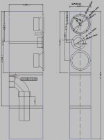
Hello, my goal is to build a MTM slim tower with the tweeter time aligned. The drivers are 2X SB15MFC-4 and RS28A. I wanted time aligned because i planned to go LR2-2.2K and wanted a wide phase matching between the W & T.
I tested the drivers on a flat baffle and estimated the offset at 22mm but still used a spacer of 16mm because that is what i had on hand.
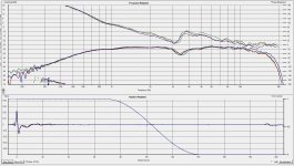
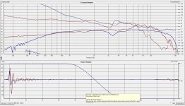
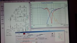
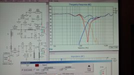
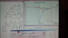
The measurements with the 16mm spacers gives a notch at 3.5khz 7db down.
I also measured at +20 and -20 degree with some phase shifts between the angles.
I do not know if this can be adressed in a Xover and how it can be done ?
At that point should i just discard the spacers ?
Take note, there is a second pair with SB13PFC-4 and SB26STCN that measured with the same result.
Regards
I tested the drivers on a flat baffle and estimated the offset at 22mm but still used a spacer of 16mm because that is what i had on hand.
The measurements with the 16mm spacers gives a notch at 3.5khz 7db down.
I also measured at +20 and -20 degree with some phase shifts between the angles.
I do not know if this can be adressed in a Xover and how it can be done ?
At that point should i just discard the spacers ?
Take note, there is a second pair with SB13PFC-4 and SB26STCN that measured with the same result.
Regards
Attachments
By default HolmImpulse aligns the impulse responses so you won't see the phase differences due to the acoustic offset between woofer and tweeter. To see the acoustic offset effects first measure the tweeter. Then go to the "Data Analysis" tab, click on the "Time zero locked" radio button and then the "Use" button. Then measure the woofer. This assumes you can switch between woofer and tweeter without moving either speaker and the mic remains untouched.
This still isn't foolproof and others have reported problems getting the same acoustic offset value using HolmImpulse when trying to repeat measurements. That's a consequence of using a single channel measurement system and the Windows OS that can cause timing differences. The best method I know about when using a single channel system is in the attachment. Hope this helps.
This still isn't foolproof and others have reported problems getting the same acoustic offset value using HolmImpulse when trying to repeat measurements. That's a consequence of using a single channel measurement system and the Windows OS that can cause timing differences. The best method I know about when using a single channel system is in the attachment. Hope this helps.
Attachments
Last edited:
Hello Thank you for the time zero lock explanation on the time zero lock use and limitations.
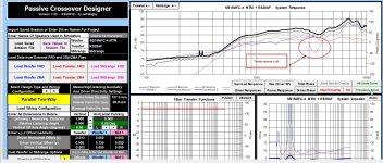
I ran the simulation on PCD and with the spacer that i used on the woofer(16mm) my tweeter is offset 4mm behind the woofer.
My real problem is with the notch of 7db that is induced by the spacers in the xover region. That would kill the frequency response in a sensitive region.
I have tried foams without any significant effect.
Is there any xover topologies that could flatten this notch ?
See attached picture. The tweeter response is in red.
I have read troel gravesen article on the effect of stepped baffle that had minor impact on frequency response but it seems that for a MTM , it is a different story.
Stepped Baffle Study
Thank you.
Attachments
Since it's MTM most likely time alignment isn't as crucial since up, down difference should cancel. I rather have flat freq resp than perfect phase matching. The other way is maybe using short waveguide would be another way to solve the problem. Also what's really important is acoustic time alignment rather than physical and by changing the slightly slope and Q you might be able to align the drivers. I would try max thickness of the spacer that allows for acoustics phase alignment and doesn't introduce the dip.
Funny, I built SB based 2way LR4 on sloped baffle to physically align the drivers but after a while playing with crossover, I realized that it would work better with less tweeter delay or on the flat baffle and x-o would be easier to design. You might also get the dip from the cone reflection. Did you try Vituix and XSim for simulations (I like XSims min phase calculator and delay options).
Funny, I built SB based 2way LR4 on sloped baffle to physically align the drivers but after a while playing with crossover, I realized that it would work better with less tweeter delay or on the flat baffle and x-o would be easier to design. You might also get the dip from the cone reflection. Did you try Vituix and XSim for simulations (I like XSims min phase calculator and delay options).
The same design that I mentioned above. Very similar freq resp, almost identical but one x-o has no delay on woofer. The second case has -0.7in woofer delay and steeper slope, the 4.2k cone break-up is reduced, the actual x-o used. In my case something about 0.4-0.5in delay would work best, the 1.4k dip comes from the cone, the 1k and 2k peaks are from baffle, there is 3k dip on tweeter that disappears off axis.
Attachments
Thank you for your suggestions.
I have both sets of measurements (with and without spacer) so I will have to go on the simulations and try with the slope and Q of the filter and see what comes out of it.
The boxes have been stained and maybe the varnish will be put on next wekend so i will not be able to measure until the boxes are finished.
Best regards