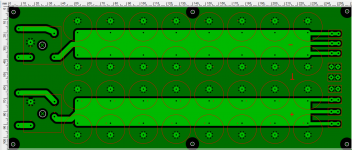
That is a double sided board with plated through holes?
Not sure what you are trying to do. Show us the schematic. You are putting the supplies in series after the rectifier, not before and use the common as the ground making a CT transformer? Do your bridges need a heat sink? Don't skimp on copper. No reason to make those little "fingers" out there.
Not sure what you are trying to do. Show us the schematic. You are putting the supplies in series after the rectifier, not before and use the common as the ground making a CT transformer? Do your bridges need a heat sink? Don't skimp on copper. No reason to make those little "fingers" out there.
Keep the two FWB supplies electrically separate. You want thermal relief on the rectifier lead, and on the outputs.
Make sure that the foil is on the bottom side of the board, and not on the component side.
The asymmetry of the rectifier blocks means that the board cannot be flipped upside down.
Make sure that the foil is on the bottom side of the board, and not on the component side.
The asymmetry of the rectifier blocks means that the board cannot be flipped upside down.
Last edited:
