Hello to all,
I am a beginner and I need your help.
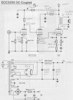
I built some amplifiers with success but the last, of which I attach the diagram (the diagram is not the mine) does not work. The voltages written are what I have measured but i don't know those correct. (I think that the 50 should work with 320V on the plate, -57.6V on the grid). I have connected a source and it plays very twisted and with much noise.
I am a beginner and I need your help.
I built some amplifiers with success but the last, of which I attach the diagram (the diagram is not the mine) does not work. The voltages written are what I have measured but i don't know those correct. (I think that the 50 should work with 320V on the plate, -57.6V on the grid). I have connected a source and it plays very twisted and with much noise.
Attachments
Ciao Urbano!
A strange thing is the link connecting the cathode of the second section of ECC32 to the 50. At the cathode of the ECC32 you measure 80V with respect to ground, at the grid of the 50 you measure a different value. How did you measure this last value?
From a first look you should raise the cathode resistor under the 50 (the 4290ohm one) to at least 4.7k.
Otherwise, a very bad design, with some problems. 0.9mA with 35Vak on an ECC32? Shame on the designer
Also some other notes you make, are very strange. Near the anode of the first ECC32 section you show 1.8mA, but on the cathode you read only 0.9mA. Where are the other 0.9mA? In the second ECC32 section's grid?
Please discharge the power supply, recheck the schematic, and re -measure your voltages. It just doesn't compute as posted.
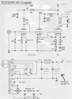
I think something like this would be better.
However, if one wants to do full DC coupling, low distortion with so low B+, power output will be very limited. The version I attach to this message can do only 1W or so.
To gain power, I would suggest to AC couple the first and the second stage, and DC couple the second and the third one. Far better results 😉
Attachments
Ciao Giaime,
the last value is measured between the grid of the 50 (anode of ECC32) and cathode of the 50 (80 - 120 = -40V)
Hi Burnedfinger,
i have discharged the power supply and rechecked the schematics, now i'm measuring the voltages then i will post them.
Also i know that they don't compute as posted... All the voltage measured are very strange...
now I use another DVTM...
- Status
- Not open for further replies.