Hi all,
Im a newbie to DIY, and need some advice on the following issue:
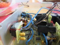
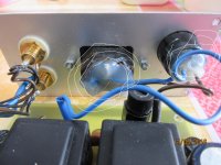
I want to improve the internal wiring of my Amity headphone amplifier and Ihave purchased some good quality cables. The thing is that once I open the amp cage, i find a couple of transparent /white big patches of what seems to be something similar to silicon, glue or some kind of electronics / thermal paste, on both sides of the amp.
These patches are covering the internal part of the mains socket, and the power switch, on one side, and what seems to be the internal part of each potentiometer ( the amp has two, one for each channel) on the other....
I can't remove the old cables and solder the new ones unless i remove these patches...but Im not pretty sure what they're used for, and if i'll have to restore ithem again , after soldering the new cables, in case they were something necessary to stick with, for rhe amp to work properly.
Are these patches some kind of glue, heath dissipator, electrical isolator....something whose mission is to keep pieces fixed and / or Isolated ??
Where could i buy them .?
I attach a couple of pics, with the patches encircled, that will probably help the experts to understand what the patch is made of.
Many Thanks in advance for your answers, guys!,!!!!
Attachments
That's a variety of silicon glue. And there's no reason to replace the AC and DC wiring. The blue wires are ground, no reason to replace any of those either. For your own safety do no mess with the AC wiring.
Assuming that replacing the signal wires will result in some sonic improvement, just replace the non-blue wires on the headphone jack and the input RCA jacks.
The silicon glue on the input pot is probably used as glue to keep the pwb from stressing the pot contacts.
Assuming that replacing the signal wires will result in some sonic improvement, just replace the non-blue wires on the headphone jack and the input RCA jacks.
The silicon glue on the input pot is probably used as glue to keep the pwb from stressing the pot contacts.
The glue on the mains socket is a cheaper method of attempting to make the live conductors safe than using Hellerene Rubber Sleeves.
remove the white/opaque insulator slpodge.
Unsolder the old mains wiring.
Get a length of 3 core flexible mains cable.
Strip out the three wires, brown for the Live, blue for the Neutral and green/yellow for the Protective Earth.
Use these universally recognised colours to rewire.
A switched Live can sometimes use a yellow wire, but that tends to be seen in lighting circuits. Decide whether you want to adopt yellow as a switched Live or stay with brown.
After you have wired all of the mains and before you connect the transformer, test your new assembly. Use a Mains Bulb Tester to power ON your project. Does the Bulb light up, or glow dimmly, or stay out completely? A transparent bulb envelope is better to see the filament.
Is the mains voltage correct across the L-N connections?
Power OFF and connect the transformer.
Repeat the Power ON test via the Mains Bulb Tester.
Once you know all is connected correctly, you can apply insulation to prevent accidental contact with any of the Live or Neural connections.
You don't want a finger, or a tool, to touch any of the mains parts.
Thank you guys for your answers.
My project consists esentially in changing the signal wires. I've got doubts about the benefits of changing the Ac/Dc wiring.
In regards to the silicon glue/insulator do you use or know a good / favourite commercial Brand? Is it available on places like amazon or specialized hifi electronics like hifi-collective? Or could it even be available on more common places like big retail stores such aswalmart or similar ones in Europe?
- Status
- Not open for further replies.

