pcb is ready from yesterday. i,m soldering parts. well i test amp with +/- 28vdc 1Α for safety. if all going good i will apply +/-42vdc.
i will tell the results and measurements at evening...
my little problem is the output transistors. i cand find right now bd911/912 and i apply bd243c/244c for these days.....
sorry for my bad english!
i will tell the results and measurements at evening...
my little problem is the output transistors. i cand find right now bd911/912 and i apply bd243c/244c for these days.....
sorry for my bad english!
Use a Mains Bulb Tester (MBT) to power up the transformer. Then continue using the MBT as you add each module to the output.
Test in stages.
Then when the bulb stays on you know it is the last stage to be added that has the error.
Test in stages.
Then when the bulb stays on you know it is the last stage to be added that has the error.
ok, 26mv/0.22ohms = 118mA, is your heatsink big enough to handle 5 watts per trannie of collector dissipation?
surely heatsink will tend to heat even at idle or no input signal.
I suggested 20mV to 22mV as the emitter resistor voltage for optimal ClassAB.surely heatsink will tend to heat even at idle or no input signal.
This equates to about 8W on +-42Vdc supply.
Using a 1C/W sink expect around 12Cdegrees rise above ambient when the amp is quiescent (no signal).
In the UK allowing for a summer ambient of 28°C gives a Ts ~ 40°C and a Tc ~ 42°C.
If that is too hot for the OP, then simply changing the emitter resistors to something a bit higher than 0r22 will give lower temperatures @ optimal ClassAB.
I suggested 20mV to 22mV as the emitter resistor voltage for optimal ClassAB.
This equates to about 8W on +-42Vdc supply.
Using a 1C/W sink expect around 12Cdegrees rise above ambient when the amp is quiescent (no signal).
In the UK allowing for a summer ambient of 28°C gives a Ts ~ 40°C and a Tc ~ 42°C.
If that is too hot for the OP, then simply changing the emitter resistors to something a bit higher than 0r22 will give lower temperatures @ optimal ClassAB.
Each channel have heatsink for 3x TO3 power transistors. i think is enough for 4x TO220 power transistors. I dont remember dimensions but i measure it later!
Another question, BD243C-244C will be withstand the voltage of +/-42vDC?
I'm asking because i dont find again the BD911-912 and i must wait after new year.
20mV/0.22R=90.9mA
90.9mA x4 (power transistors) = 363mA
363mA = http://iowaadguy.files.wordpress.com/2012/06/101192074.jpg
I'm afraid that!!!
Another beginner question.....
In a datasheet, which tells us how the semiconductor withstand the bias current?
those amplifiers have built are biased to 7.5mV (+/-10%) (34mA) on emitter resistor.
some news. i have 56R /10w safety resistors at supply rails, those resistors are getting hot without load and input. and to output i have 22vDC!!!
bias pot are to maximum level (2kohm) and if reduce resistance the dc remain on output.... maybe the problem is on differential amp. we will see....
bias pot are to maximum level (2kohm) and if reduce resistance the dc remain on output.... maybe the problem is on differential amp. we will see....
some news. i have 56R /10w safety resistors at supply rails, those resistors are getting hot without load and input. and to output i have 22vDC!!!
bias pot are to maximum level (2kohm) and if reduce resistance the dc remain on output.... maybe the problem is on differential amp. we will see....
that's because your circuit is flawed....
you need to adjust your tail current so that about 0.6 volts
appear at the base of your VAS trannie...
either you ditch the current mirror load for a load resistor,
or you put emitter resistor on your VAS to make things right...
Or with the amount of tail current you have .....
Change R3 and R4 to 39ohm (important)
Change R5 and R6 to 100 ohm
Change R8 to 3.9kohm (important)
Change R3 and R4 to 39ohm (important)
Change R5 and R6 to 100 ohm
Change R8 to 3.9kohm (important)
Those resistors drop the supply voltage.some news. i have 56R /10w safety resistors at supply rails, those resistors are getting hot without load and input. and to output i have 22vDC!!!
bias pot are to maximum level (2kohm) and if reduce resistance the dc remain on output.... maybe the problem is on differential amp. we will see....
You end up with the WRONG voltage on the supply rails.
A complete waste of effort.
They don't save the assembly if there is a mistake in wiring or component orientation.
This is a Destroyer recommended method.
It is wrong. Ignore him.
Use a Mains Bulb Tester.
Those resistors drop the supply voltage.
You end up with the WRONG voltage on the supply rails.
A complete waste of effort.
They don't save the assembly if there is a mistake in wiring or component orientation.
This is a Destroyer recommended method.
It is wrong. Ignore him.
Use a Mains Bulb Tester.
you are right! bulb tester are more good from resistors!
So, i will test everything, the amp isnt go......
bulb lighting and on rails i have voltage +/-8vDC 😕
there isnt short circuit on board and nothing is burned up (transistor, resistor etc).
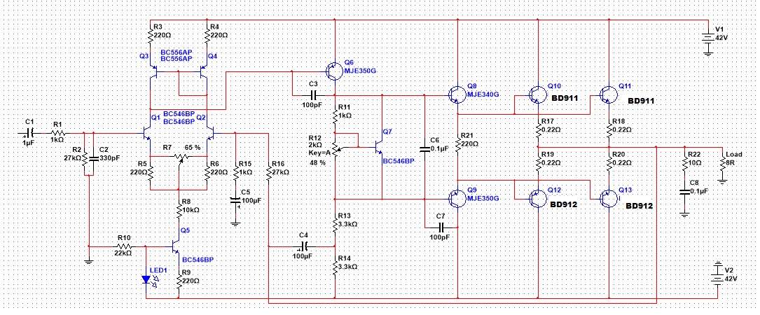
Take a snapshot from schematic....
In simulator is working perfect! that amp it's going me mad!!!


bulb testers save you a lot of grief, it tells you if your circuit is working closest to normal as any abnormality and you get a fully lit bulb...
saves you also from tedious and potentially expensive repairs...
now about simulators, time and time again i have seen simulators come up with good results although in actual situation turns out bad...
this is not the first time i have seen simulators return good results even thought there are glaring mistakes in the circuit....
in another forum, they were turning out very good simulator results until i pointed out the mistakes in circuit biasing....
so what to do?, first get your biasing correct to begin with then use the simulator to fine tune your work...
Happy new year guys!!
Yesterday i find the error, idle current of Q1-2-3-4 was too high.
When im connect power supply, that transistors are blow up....
Q6 same problem....
Corrections of schematic are is:
R3-4 = 10R (but i want try and 39R too, yesterday i was try 39R without results)
R23 = 10R
R11 = 600R
R13-14 = 3.9k
R21-22 = 220R (here added two resistors connected to output from single resistor at emitters)
I have some doubts about R23, maybe is too low but i'll try different resistance in real life.... In multisim i see 53mv across R23.
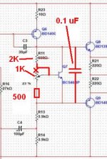
The way you have your bias pot wired in is very scary. At the extreme of rotation where bias current is maximized, you'll have Q-current of 1.8 Amps! With any drive, it will become insanely high from there as the Vbe multiplier will be cut-off.
R11 is also kind of on the low side. Attached picture has a safer bias arrangement.
1. R11 at 2K is more appropriate
2. with re-wiring, if pot opens, quiescent current goes to low, not to catastrophe
3. added 0.1 uF helps high freq stability
4. added 500 Ohm resistor limits max bias current (maybe still a little high, but at least it leaves the Vbe multiplier working)
Update My Dynaco
Akitika GT-101 Audio Power Amplifier Kit
Attachments
Hi
Your r8 does not need to be there. The emitter resistors in the input stage current mirror are too high for the tail current. I don't think 5mA is too high necessarily, but the mirror emitter resistors would drop 0.500mV and as there is only one Vbe following, your mirror transistors are nearly saturated. I'd keep the bias current as is but change the emitter resistors to drop 100mV (47 ohms).
Also add a limiting resistor in series with the Q_current bias adjust pot. The max voltage you need is 2.4v so the min. resistance would be around 330 ohms with 1k base-collector. Add a 330 ohm series resistor to stop the Q-current from taking off.
The Vbe multipler adjustment VR is wired correctly in post35. Going to open wiper changes the bias voltage to minimum.
But do add in the limiting resistor. 330r to 500r is about right.
The mirror emitter resistors perform better when much higher value. try 100r to 1k
BUT, the VbeVAS + Vr23 needs to be MUCH higher to allow this to work.
The mirror will be very close to saturation conditions and keeping R3+4 low helps.
Using D.Self's EF added to the VAS is better for this style of amplifier.
Have you read S.Groner?
The way you have your bias pot wired in is very scary. At the extreme of rotation where bias current is maximized, you'll have Q-current of 1.8 Amps! With any drive, it will become insanely high from there as the Vbe multiplier will be cut-off.
R11 is also kind of on the low side. Attached picture has a safer bias arrangement.
1. R11 at 2K is more appropriate
2. with re-wiring, if pot opens, quiescent current goes to low, not to catastrophe
3. added 0.1 uF helps high freq stability
4. added 500 Ohm resistor limits max bias current (maybe still a little high, but at least it leaves the Vbe multiplier working)
Update My Dynaco
Akitika GT-101 Audio Power Amplifier Kit
Hi, 0.1uF exsist, but i forget to add in multisim.
R11 for 2k is dissaster! in this way i blow up the BD911-912.... Too much current!
Hi
Your r8 does not need to be there. The emitter resistors in the input stage current mirror are too high for the tail current. I don't think 5mA is too high necessarily, but the mirror emitter resistors would drop 0.500mV and as there is only one Vbe following, your mirror transistors are nearly saturated. I'd keep the bias current as is but change the emitter resistors to drop 100mV (47 ohms).
Also add a limiting resistor in series with the Q_current bias adjust pot. The max voltage you need is 2.4v so the min. resistance would be around 330 ohms with 1k base-collector. Add a 330 ohm series resistor to stop the Q-current from taking off.
with R8 in and out to circuit i dont see differencies....
R3-4 should be 47ohms?
The Vbe multipler adjustment VR is wired correctly in post35. Going to open wiper changes the bias voltage to minimum.
But do add in the limiting resistor. 330r to 500r is about right.
The mirror emitter resistors perform better when much higher value. try 100r to 1k
BUT, the VbeVAS + Vr23 needs to be MUCH higher to allow this to work.
The mirror will be very close to saturation conditions and keeping R3+4 low helps.
Using D.Self's EF added to the VAS is better for this style of amplifier.
Have you read S.Groner?
R11 Sould be 330 to 500R right?
R3-4 as was in the original schematic for the beggining and will see...
For R23 i try 500 to 1k..... With bulb tester i dont afraid, i'm find the solution....
Thank all of you guys... i will post tomorrow, with good results i hope...
No i dont have read S.Groner... Do you have a link?
- Status
- Not open for further replies.
- Home
- Amplifiers
- Solid State
- Help for quiescent current adjustment