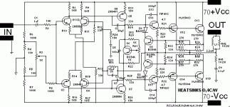
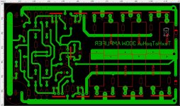
Add a link from Vbe wiper to top of R21
Add provison for base stoppers to the drivers and outputs.
Add supply rail decoupling, lot's of it.
R22 is too high. Max output of Vbe is ~3.2times Vbe and you may need just over 4times Vbe to fully turn on the output stage.
Tip41c have a 100Vce rating. They are likely to blow up with ±70Vdc supply rails.
Optional changes:
R23 will dissipate ~280mW. Consider replacing it with a series string of 1k2, or 1k1 resistors.
Think about replacing R12 & R13 with CCS.
And replacing R4 & R5 with small signal diodes.
No RF attenuation filter.
C5 will remove much of the bass and make the amplifier behave weirdly when presented with extreme LF signal.
C1 will pass extreme LF to the amplifier. You need to get the ratio of C1:C5 correct..
Last edited:
Add up the resistances in your NFB route. Apply the maximum output voltage (no load) and find the maxium current.
Then apply the standard formula for power
P=IV=I²R=V²/R
Then apply the standard formula for power
P=IV=I²R=V²/R
I will connect a transistor which will be on the radiator in transistors with wire
What do you think about 1: 1 ratio C1 and C5 both 100uf?
And one 470pF from IN to GOUND ?
NO !
C5>C1*{R1+R2 +R3/4}*sqrt(2)/R24
i.e. C5>{10k+100k+250}*1.414/150 >1039uF
use 1500uF, if you want to keep C1=1uF
Connect Crf from the right side of R1 to the Signal Return located between R4 & R5. Note this is not a ground. This point is where your signal return wire connects. It is an INPUT not a GND !
Oh, just realised. Your supply rail ripple needs to be attenuated before it injects ripple into your input stage.
You need some C to form an RC on both the +ve side and -ve side of that bias circuit. These caps will connect to the speaker return/power ground, whereas the R4 & R5 (diodes if you replace them) do not connect to the Speaker Return.
Consider splitting R6 & R7 into two 51k. attach the C (10uF) to the junction and take that to the Speaker Return.
Then add another C (1uF to 10uF) at the junctions with R4 & R5 and take these C to either Speaker Return, or to Signal Return. I'm not sure which will be better.
Last edited:
By this formula i have 1039.29. But where is C1 ? What if i want to be 10uf ? C5 is still bigger 1500>10 ...
C1 is on your schematic. It is shown as 1uFBy this formula i have 1039.29. But where is C1 ? What if i want to be 10uf ? C5 is still bigger 1500>10 ...
If you change C1 to 10uF, then C5 becomes >10392uF
- Status
- Not open for further replies.
- Home
- Design & Build
- Construction Tips
- Help for PCB developing


