Not about the fb per se, but the amount of feedback chnages when you chnge the volume. The feedback is determined by the ratio of the 150k to the impedance at the grid, seen from the 150k.
And that grid impedance changes with the position of the volume control.
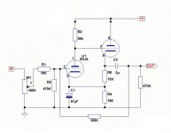
Disregarding R2 for the moment, if the level control is at zero, the feedback factor is 150k/10k. If the level control is at the top, the fb factor is 150k/110k.
A high feedback factor like 150k/110k could give stability issues, hard to say.
I wouldn't use this circuit in this way.
Jan
And that grid impedance changes with the position of the volume control.
Disregarding R2 for the moment, if the level control is at zero, the feedback factor is 150k/10k. If the level control is at the top, the fb factor is 150k/110k.
A high feedback factor like 150k/110k could give stability issues, hard to say.
I wouldn't use this circuit in this way.
Jan
yes, but only when the source impedance were infinite ...... If the level control is at the top, the fb factor is 150k/110k.
Jan
in case of a more realistic source - say 1k - the lowest fb factor is with the pot in the middle, 50k // 50k = 25k + 1k, so the spread is much smaller between 150k/10k and 150k/36k.
Last edited:

In this circuit, the pot should have a relatively low value, and R1 should have a relatively high value.
For example, a 10k pot, and R1 = 50k. Adjust the value of the 150k feedback resistor accordingly.
For example, a 10k pot, and R1 = 50k. Adjust the value of the 150k feedback resistor accordingly.
Not directly answering your question, but hopefully this will be helpful to you...
In the schematic, you have the 6DJ8 grounded cathode section with pins 6,7,8 used as the cathode follower. If you look at 6DJ8 data sheet, that triode section has a maximum cathode to heater voltage of only 50V. I'd recommend using the 6DJ8 grounded grid section with pins 1,2,3 for the cathode follower, as that has a maximum heater to cathode voltage of 130V. The cathode follower will have its cathode sitting at over 75V DC.
Also, you will want a series grid stopper resistor between the plate of V1 and the grid of V2, to suppress the possibility of oscillation. Physically locate that resistor as close to the grid of V2 as you can.