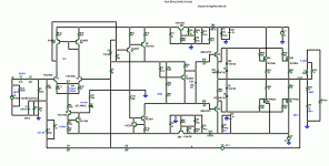
guys help me about the design in the power amp stage.
I don't know what I'm doing wrong
requirements for the power amp stage
here is what I have gone so far, the pre amp stage I think is good,
[image]http://i15.photobucket.com/albums/a369/panops/pleasehelp.jpg[/image]
I don't know what I'm doing wrong
requirements for the power amp stage
- single stage mosfet
- voltage dc bias lessthan 50v
- able to drive an 8ohm speaker
- class ab (push pull)
here is what I have gone so far, the pre amp stage I think is good,
[image]http://i15.photobucket.com/albums/a369/panops/pleasehelp.jpg[/image]
guys help me about the design in the power amp stage.
I don't know what I'm doing wrong
requirements for the power amp stage
- single stage mosfet
- voltage dc bias lessthan 50v
- able to drive an 8ohm speaker
- class ab (push pull)
here is what I have gone so far, the pre amp stage I think is good,
[image]http://i15.photobucket.com/albums/a369/panops/pleasehelp.jpg[/image]
here is one for you..(below)
150w/8r
doug self "blameless based"
300w 4R
runs from 45-65V rails
The voltage stage is done but the artwork for the MOSFET power stage is under development.
OS
thanks sir for the help, but what i want is just to fix or improve my schematic (below)
here's the link http://i15.photobucket.com/albums/a369/panops/pleasehelp.jpg
why did you pick that topology ? it will not be audiophile no matter what you do with it. If simplicity is your concern , the least complicated you can do is a bootstrapped differential based topology. Like my BX with IRF's as OP's .. it only has 6 transistors not counting the outputs. I am not saying you circuit will not work , but it is 1960 tech. find just 1 recycled junk stereo receiver with a 30-0-30VAC trafo transformer and for $50 USD you can have 2 -60w/ch nice class AB. 2 Diodes for bias is reserved for barbie toy disco amplifier.
OS
OS
You use 20 Volt supply, which
equals +/- 10 Volt only.
For HEXFET (mosfet) output follower
we get a 4-5 Volt drop. This is a direct loss.
Which leaves 5-6 Volt peak output across speakers.
So, in best case you can get 2.25 Watt RMS into 8 Ohm
I suggest you double supply voltage for output HEXFET.
40 Volt (+/-20V) or 50 Volt (+/-25V) is not too much.
It still is a power amplifier in the lower wattage range.
At +/-25 Volt the output will be 20-25 Watt into 8 Ohm.
I show down here an example how to do.
I use your idea, with small changes.
One thing.
Your two 1N4002 diodes makes the amp run in Class B.
That is, there is no idle current in MOSFET.
Put an Ampere-meter in that stage, and you can see how much current at no signal.
For normal Class AB we can use 100 mA at idle.
For this you need more than the 2 Volt those 1N4002 gives.
You need like 8-9 Volt maybe. Depending on what HEXFETs.
Each MOSFET need 4-4.5 Volt for turning on and give 100 mA.
For +/- 25 Volt then IRF540/IRF9540 may do well. They are TO-220
If you can find the 'N' variants so those are to prefer: IRF540N/IRF9540N
For higher Supply voltage I would go for IRFP240/IRFP9240 in TO-247
which for example Nelson Pass uses often.
=======================
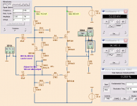
Diagram.
I show how you can use one extra MOSFET + Trimpotentiometer to set idle current.
I have used ~100 mA idle operation.
The output shown is at 14.142 Vrms which is 25 Watt in 8 Ohm.
THD:
1 Watt = 0.455%
25 Watt = 0.203%
The bandwidth is: 2.5 Hz - 3,500,000 Hz (3.5 MHz)
This is not too bad for no feedback.
If this stage was put inside a global feedback loop, it would do just fine.
Attachments
These are not the type of mosfets that are well recieved in the audiophile arena. They are not very linear and those who use them as if they were BJT's or lateral fets are often disappointed. (of course that includes just about everyone🙄 ) This is not my opinion but they have to be used properly as they are not designed to be like BJT's or work like them either. They are totally different. Read Bob Cordell's EC mosfet paper here. It is based on some of Hawksford's work and if you understand it, then build it, you will be most pleased. Although it works, it will complicate your circuit a bit. It is my opion that you can "create" a better output follower stage with those types of transistors, although it may require a couple local loops to be built into the circuit. The highish frequency distortion components created from those types of devices can contaminate a global loop.
If simple is what your after, I'd go with BJT OPS. However, I suggest to follow Bob's paper, at least the OPS, and try the fets, I think you will be impressed.🙂

If simple is what your after, I'd go with BJT OPS. However, I suggest to follow Bob's paper, at least the OPS, and try the fets, I think you will be impressed.🙂

Last edited:
- Status
- Not open for further replies.
- Home
- Amplifiers
- Solid State
- help for my power amp stage

